Creating an Anatomical Model for SlicerROS2
Overview
This tutorial walks through creating 3D anatomical surface models from a CT image using 3D Slicer and the TotalSegmentator extension. The resulting STL files can be loaded into SlicerROS2 as anatomical reference models during robot-assisted procedures.
The workflow has five main stages:
- Load a CT image in 3D Slicer
- Run TotalSegmentator to automatically segment anatomy
- Select segments of interest and hollow them
- Export the segments as 3D surface models
- Clean up the scene and save as STL files
Part 1: Load a CT Image in 3D Slicer
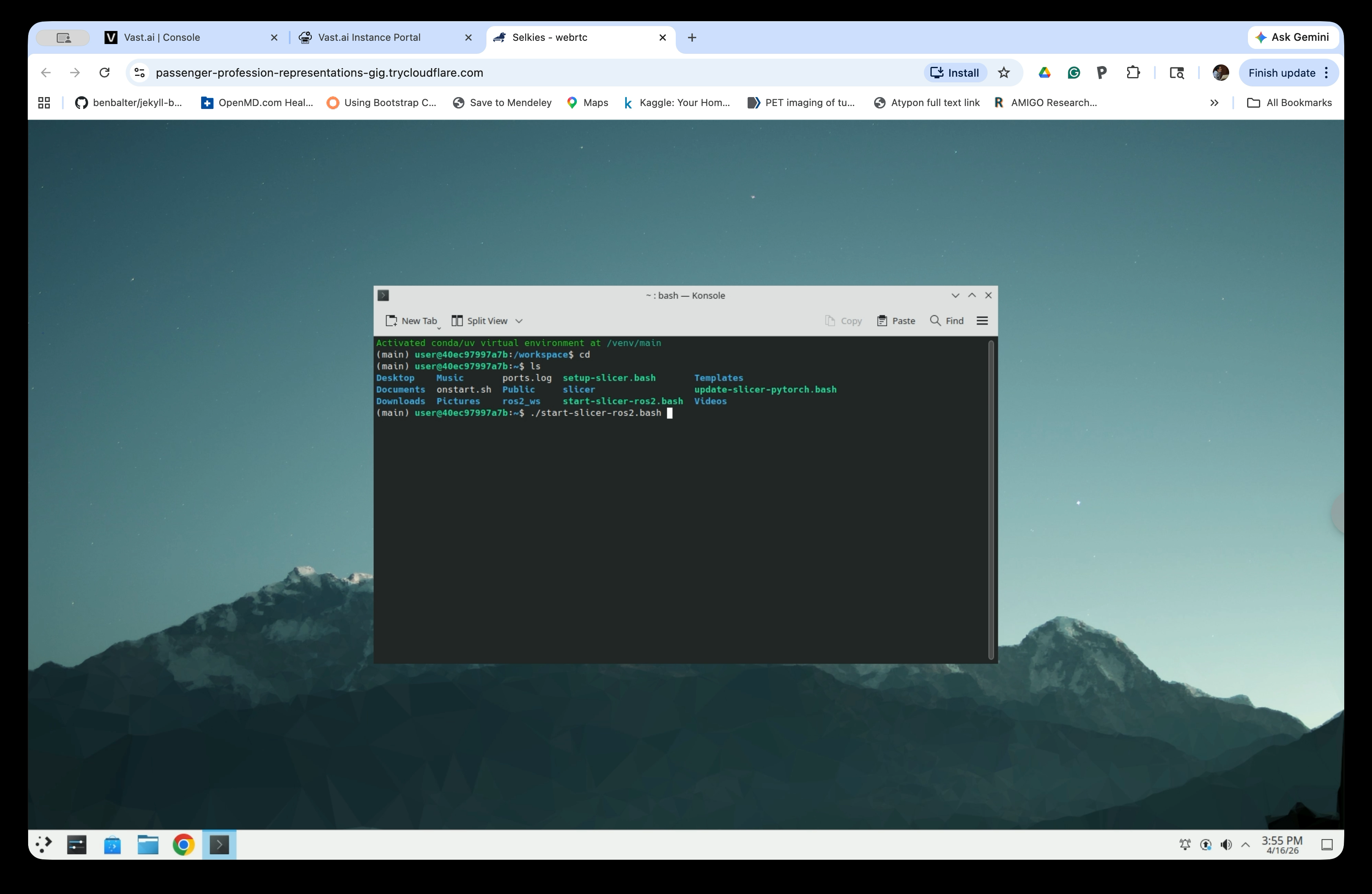
Step 1: Start 3D Slicer
Open a terminal in the Linux desktop and run the startup script:
source ~/ros2_ws/install/setup.bash
ros2 launch slicer_ros2_module slicer.launch.py
Step 2: Open the Sample Data Module
Once 3D Slicer opens, go to File → Download Sample Data to open the Sample Data module.

Step 3: Load the CTChest Dataset
In the Sample Data panel, click the CTChest thumbnail to load it. Slicer will download and load the CT chest scan.
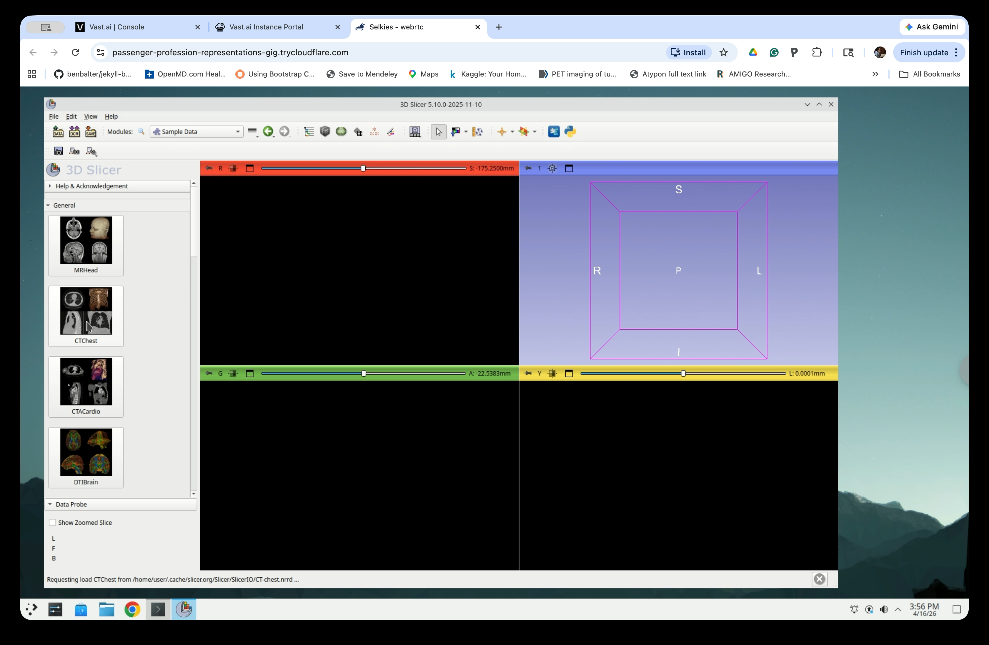
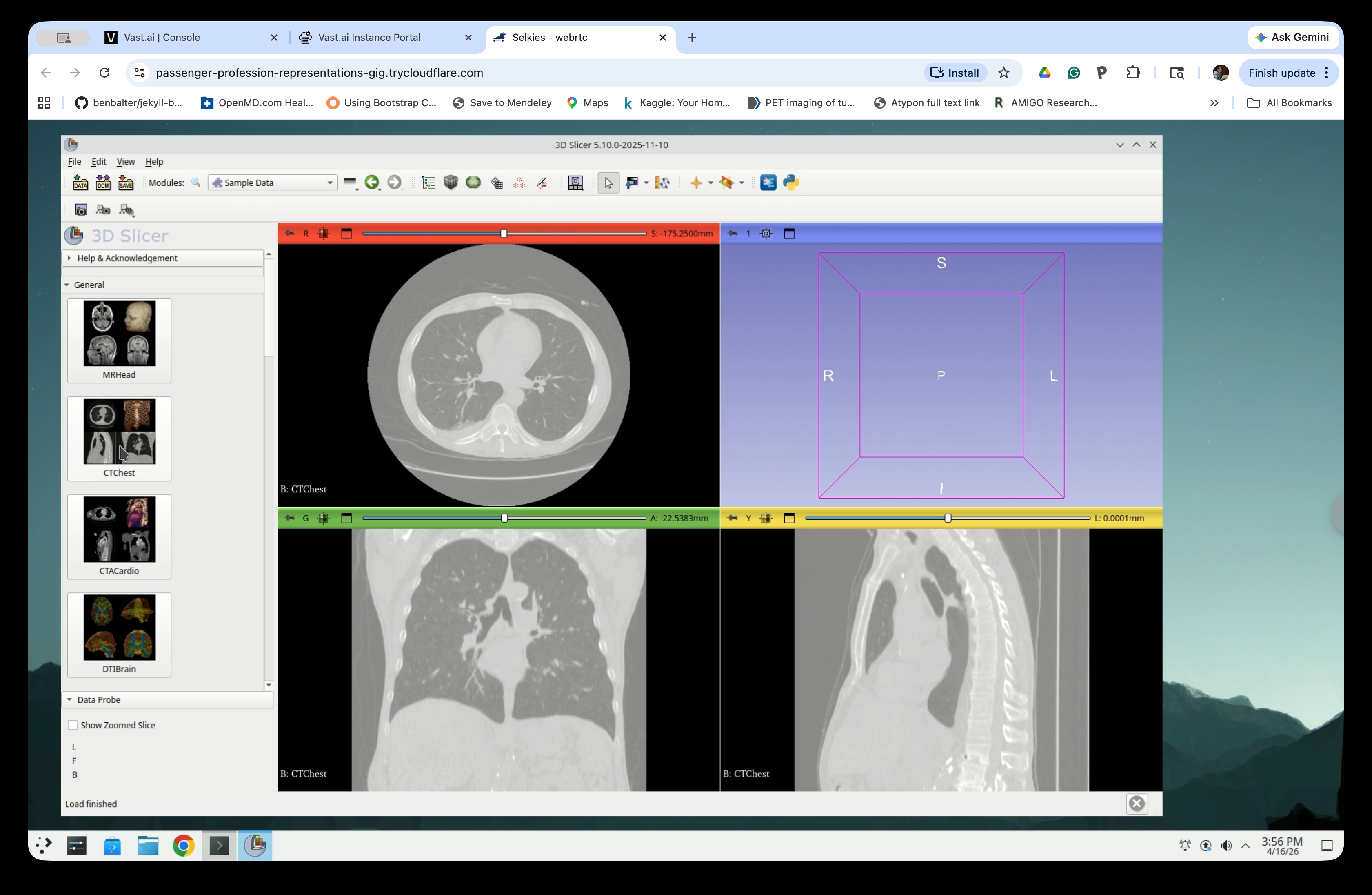
Step 4: Verify the Image is Loaded
The CT image will appear in the three slice views (axial, coronal, and sagittal). Verify that the chest anatomy is visible before continuing.
Part 2: Run TotalSegmentator
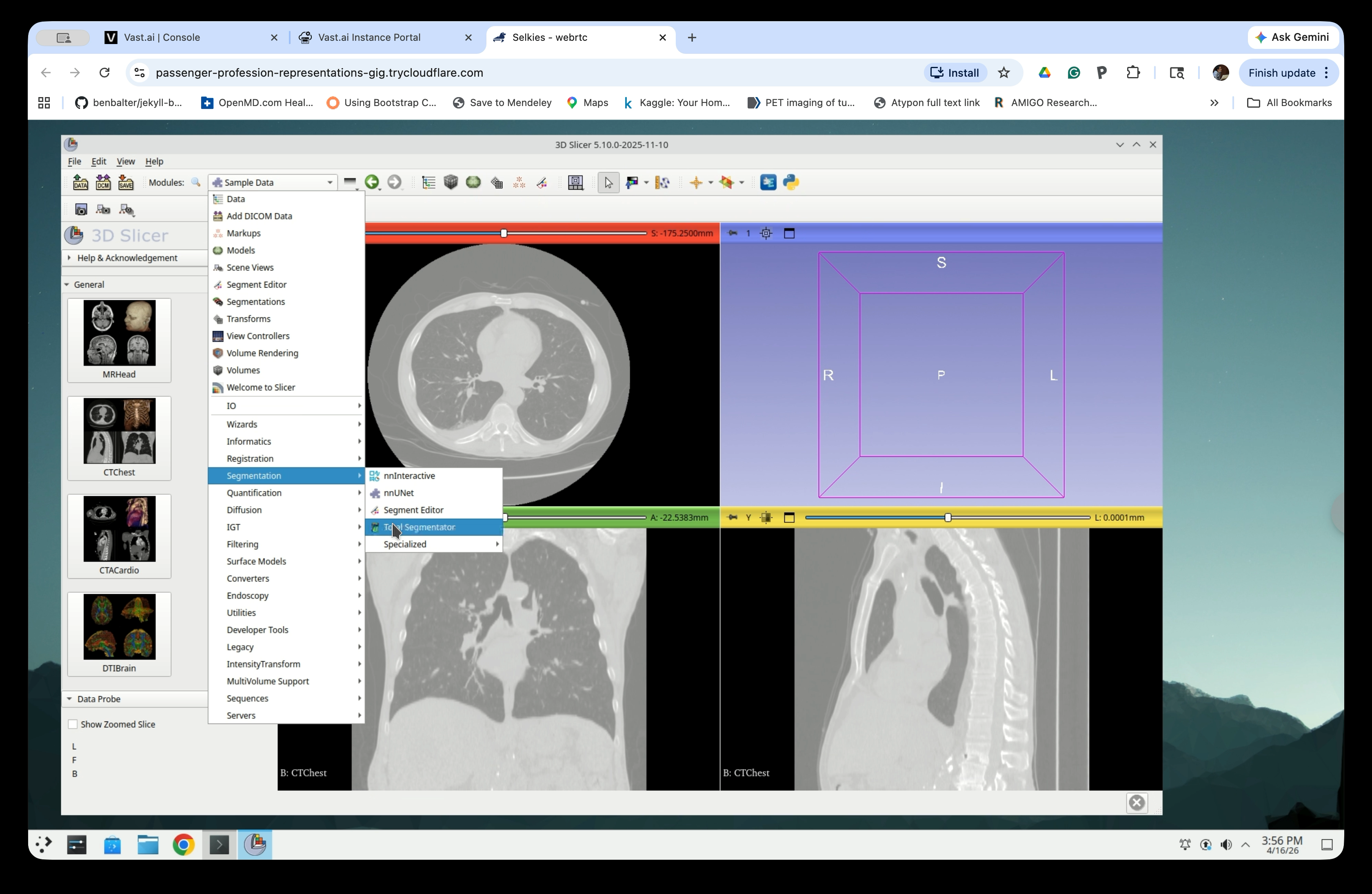
Step 5: Open the TotalSegmentator Module
From the Modules menu, navigate to Segmentation → TotalSegmentator.
Step 6: Configure and Run Segmentation
In the TotalSegmentator panel:
- Input volume: CTChest
- Segmentation task: total
- Speed: Normal
Click Apply to start the segmentation.

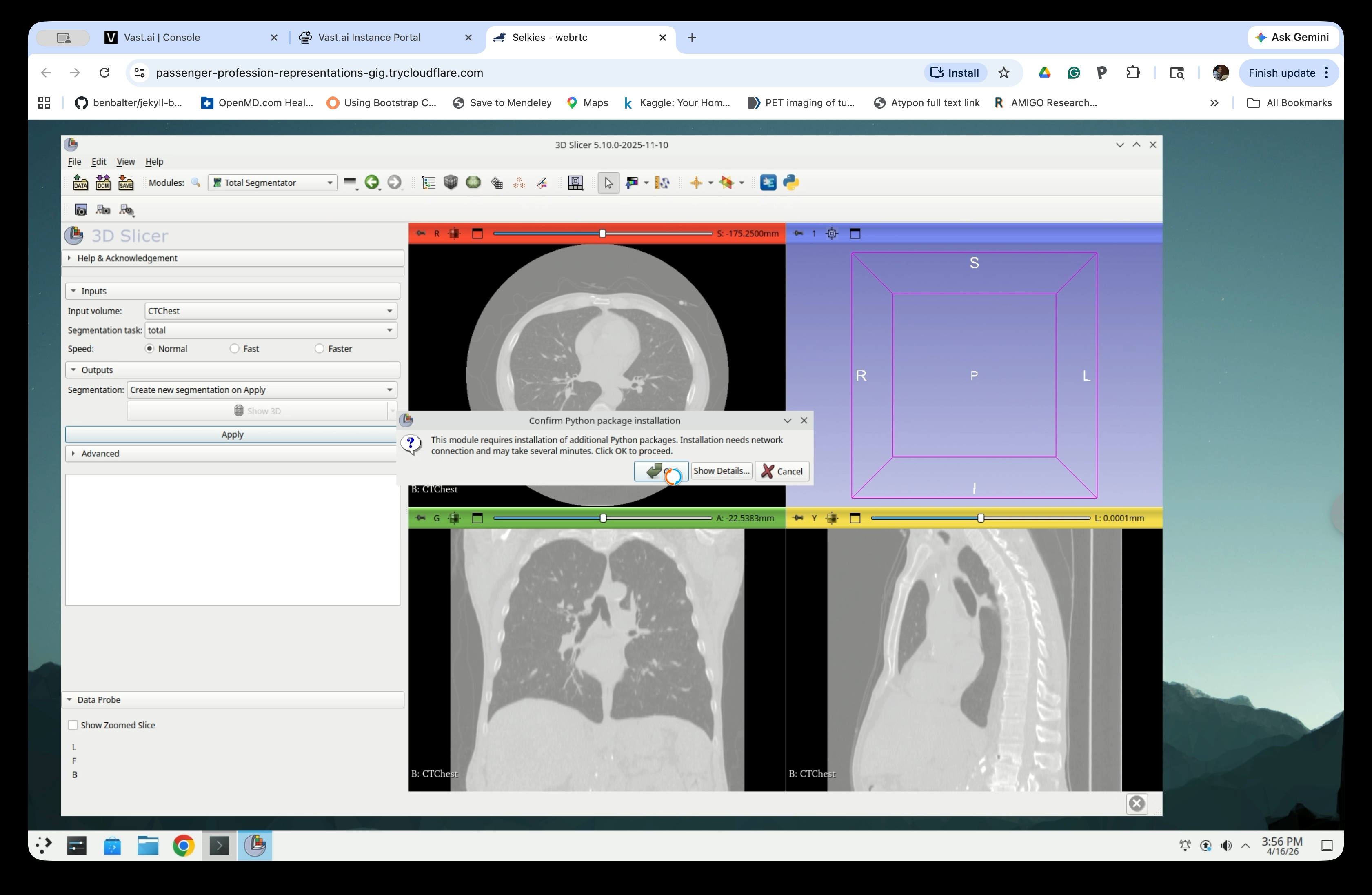
Step 7: Confirm Python Package Installation
If this is the first time running TotalSegmentator, a dialog will appear asking to install required Python packages. Click OK to proceed.
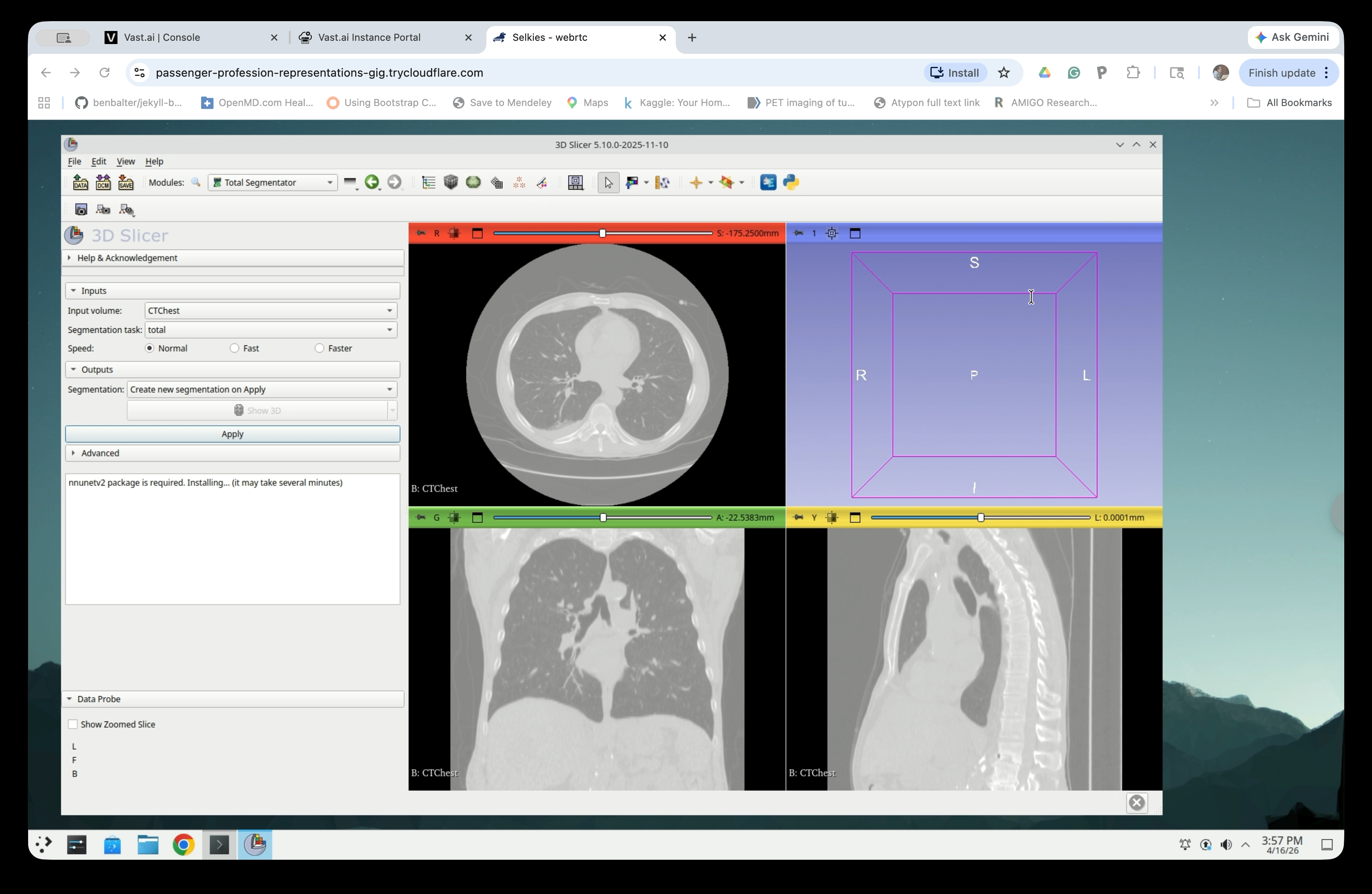
Step 8: Wait for Package Installation
Slicer will display a status message while installing the nnunetv2 package. This step may take several minutes and only needs to be done once.
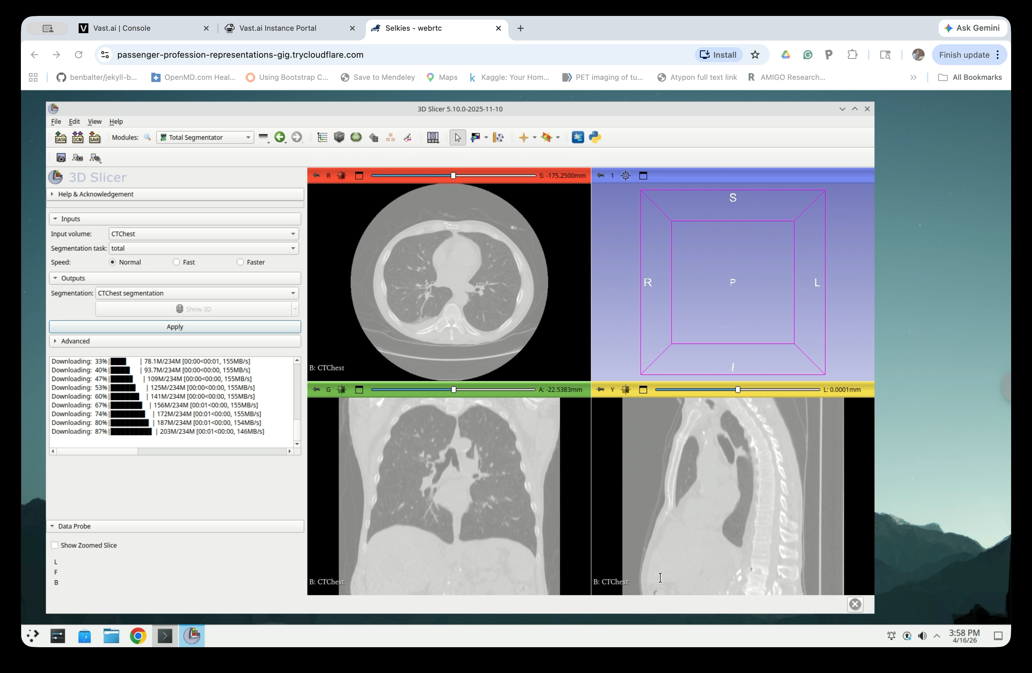
Step 9: Wait for Segmentation to Complete
Once packages are installed, TotalSegmentator will download model weights and run the segmentation. Progress is shown in the panel. This typically takes 2–5 minutes.
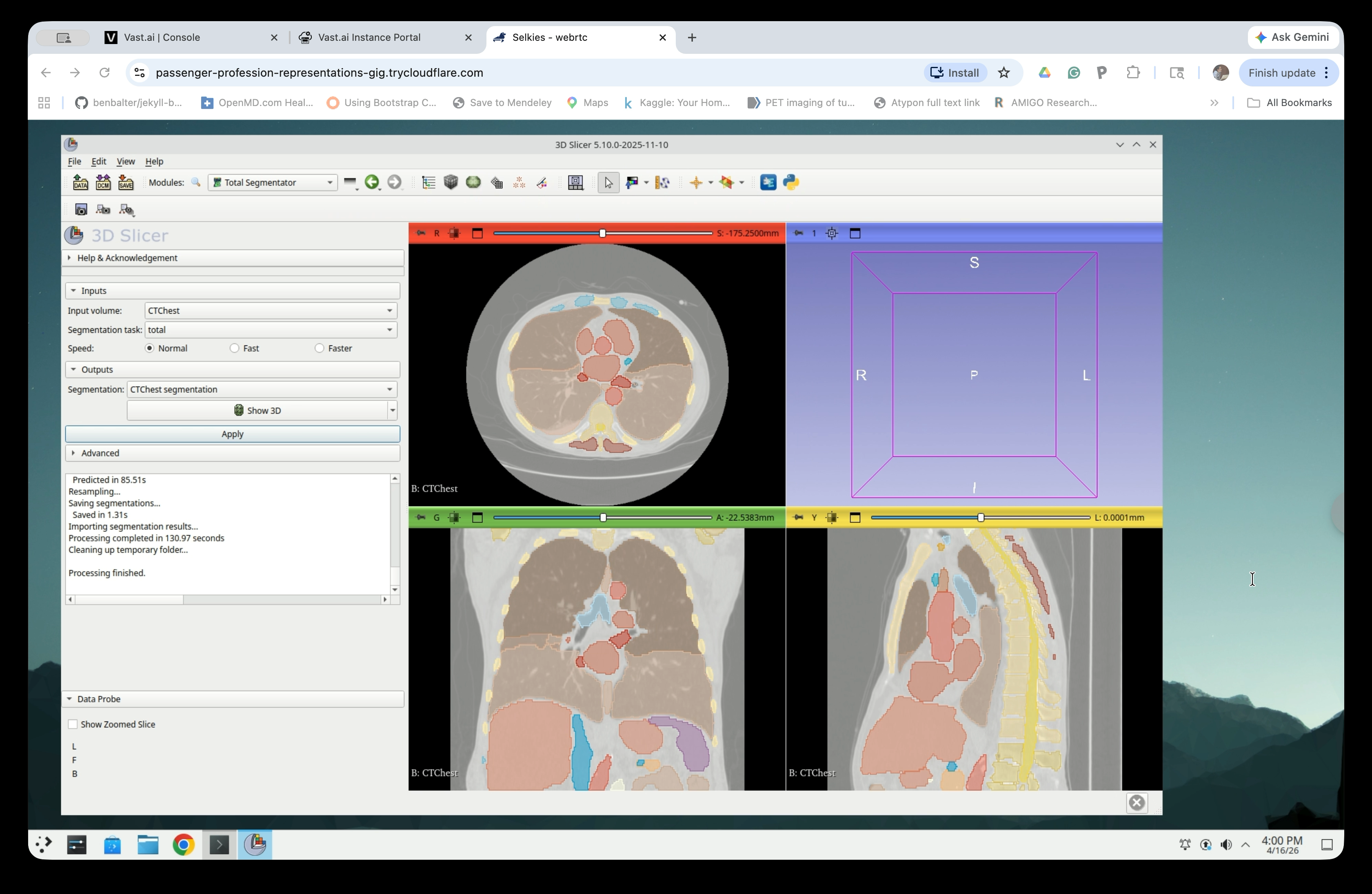
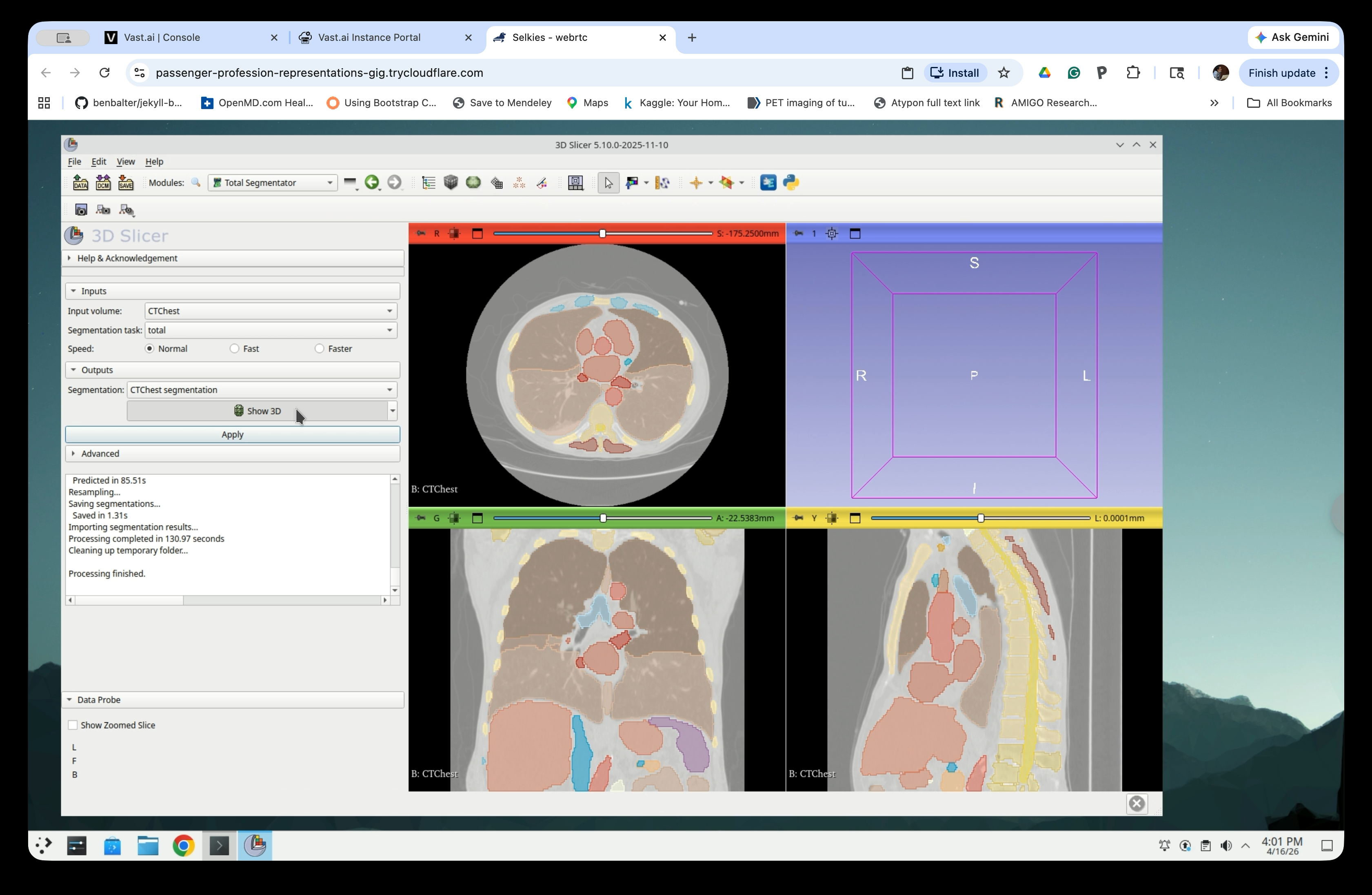
Step 10: Review Segmentation Results
When complete, the status log will show “Processing finished.” Colored segment overlays will appear on all three slice views.
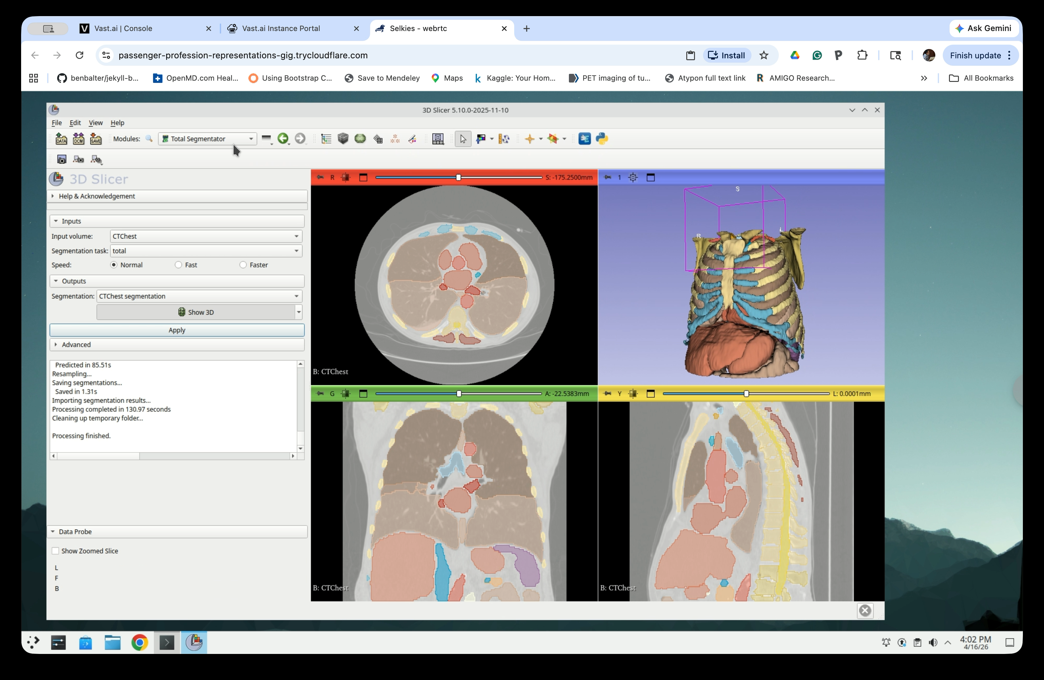
Step 11: Enable 3D View
Check the Show 3D checkbox in the Outputs section to display the segmentation in the 3D view.
The 3D view will now show the segmented anatomy, including the ribcage, heart, and major vessels.
Part 3: Select Segments of Interest
Step 12: Switch to the Segmentations Module
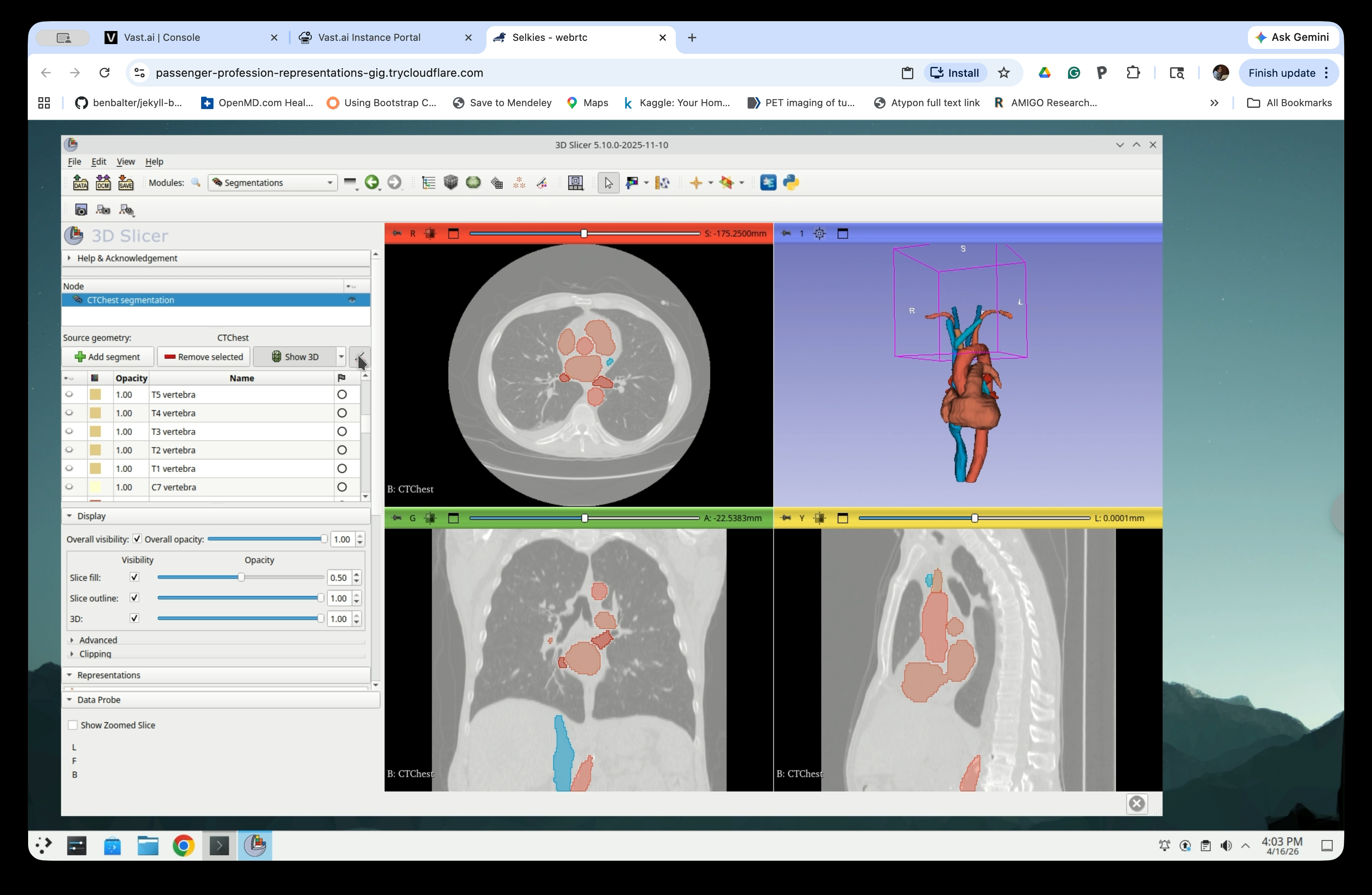
Open the Modules menu and navigate to Segmentations.

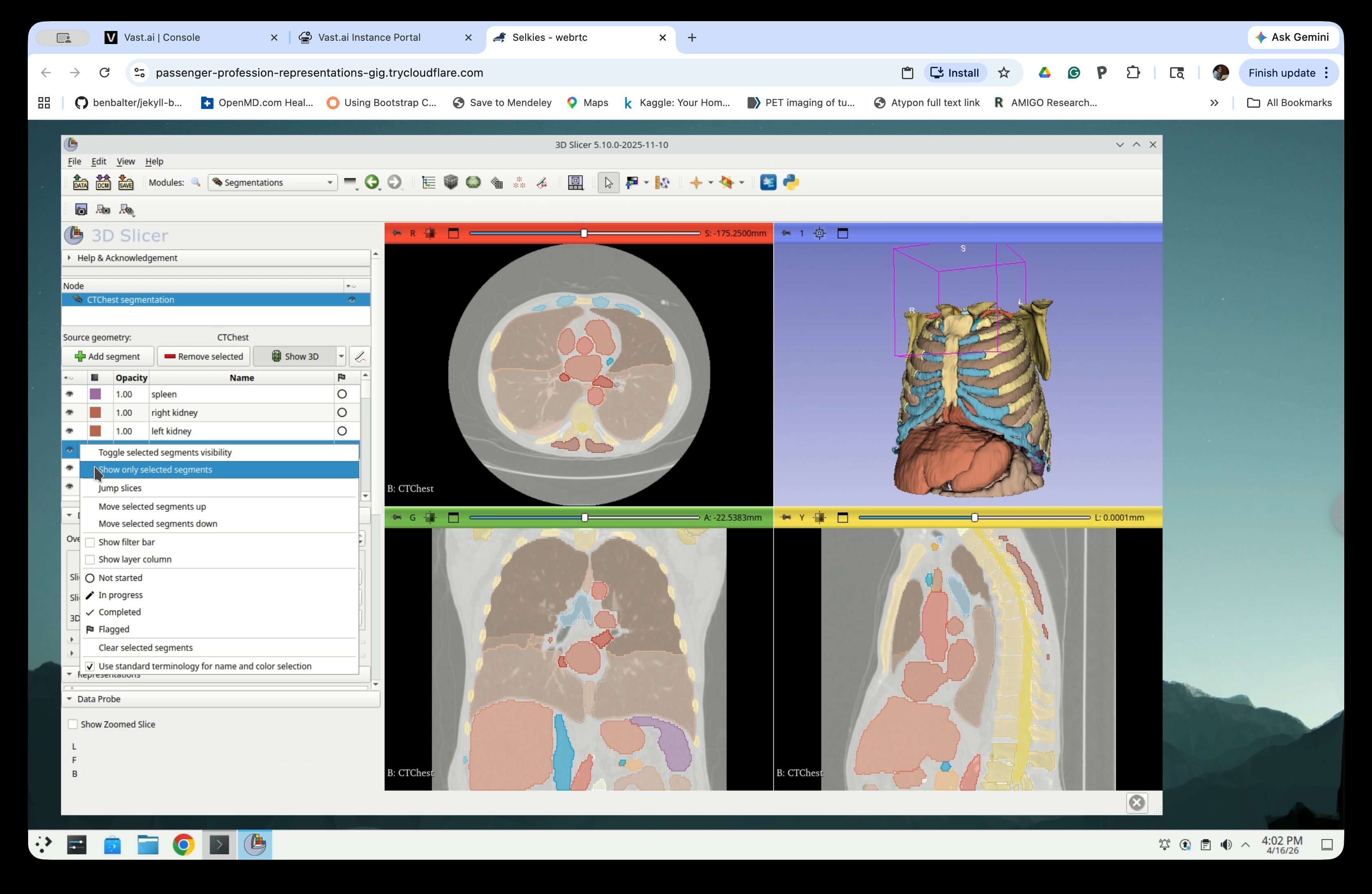
Step 13: Show Only Selected Segments
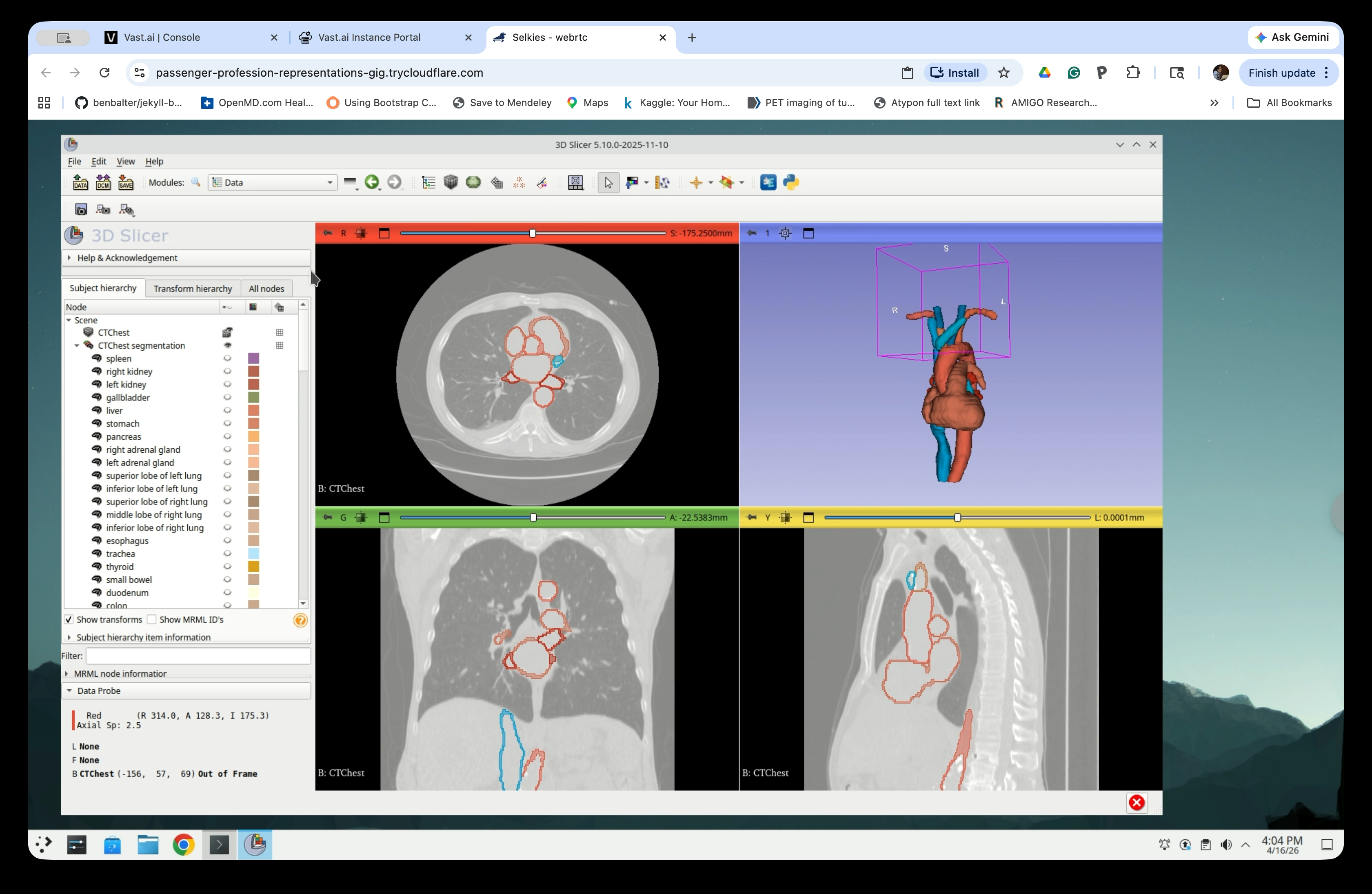
In the Segmentations panel, the full list of segmented structures is shown. To isolate specific structures, select them in the list, then right-click and choose Show only selected segments.
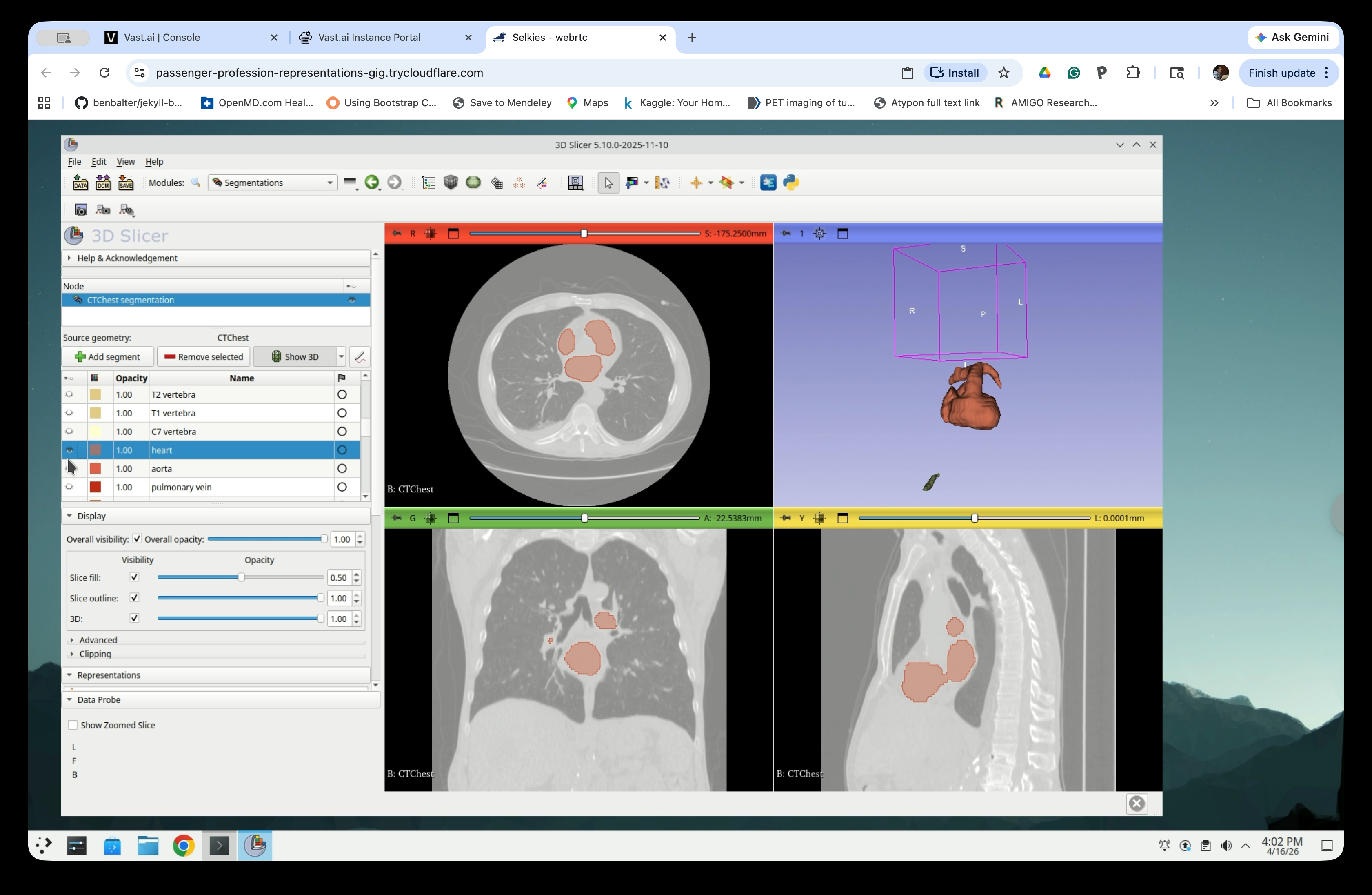
Step 14: Select the Structures You Need
Scroll through the segment list and select the anatomical structures relevant to your application. For this tutorial, select the heart, aorta, pulmonary vein, and major vessels, though the aorta is the only structure we need for the catheter simulation. The 3D view updates to show only the selected structures.
Part 4: Hollow the Segments
Hollowing the segments converts solid volumetric segmentations into thin-shell surface models, which are more suitable for 3D printing or visualization.
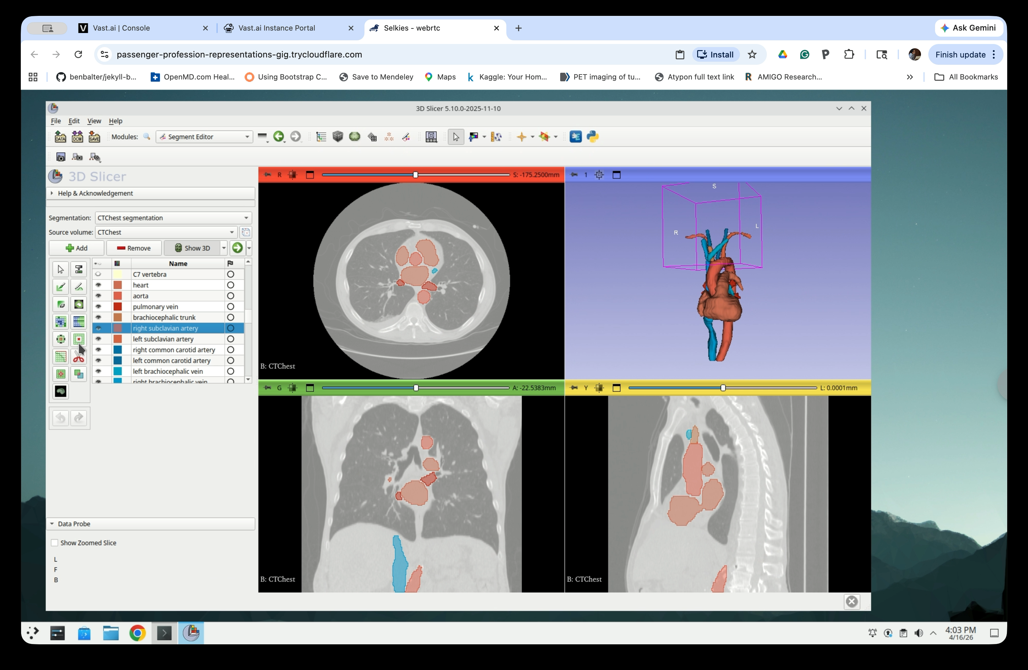
Step 15: Switch to Segment Editor
From the Modules menu, navigate to Segment Editor (or click the Segment Editor button in the toolbar).
Step 16: Open the Hollow Effect
In the Segment Editor, select any segment that are visible (i.e., one selected in the previous step in the Segmentations) from the list. Then click the Hollow effect button in the effects toolbar.
Step 17: Configure Hollow Settings
Set the following parameters:
- Use current segment as: inside surface
- Shell thickness: 3.00 mm
- Check Apply to visible segments to hollow all visible segments at once
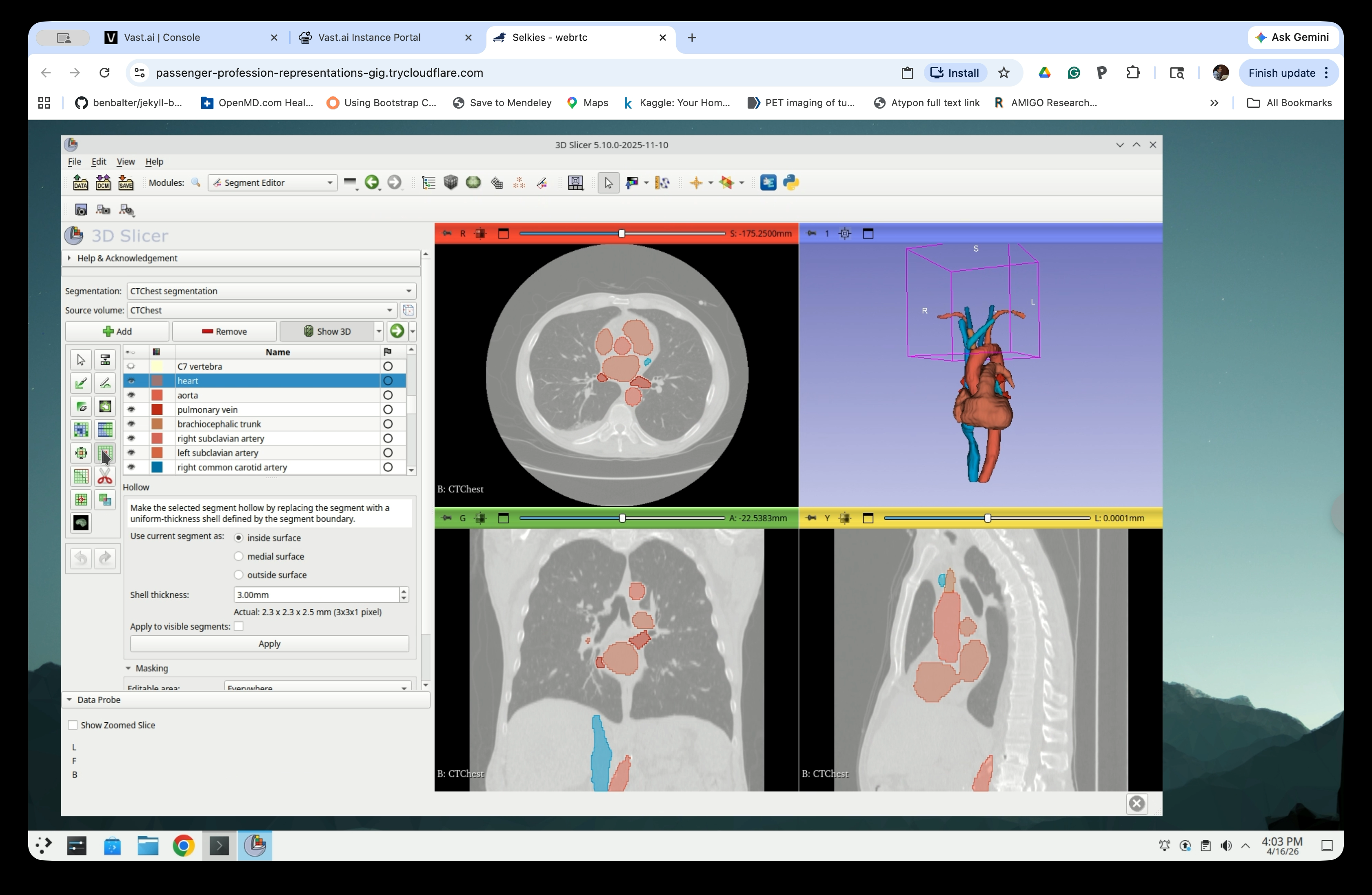
Step 18: Set Apply to Visible Segments
Select the Apply to visible segments checkbox to process all currently visible segments.

Step 19: Apply the Hollow Effect
Click Apply to run the hollow operation.

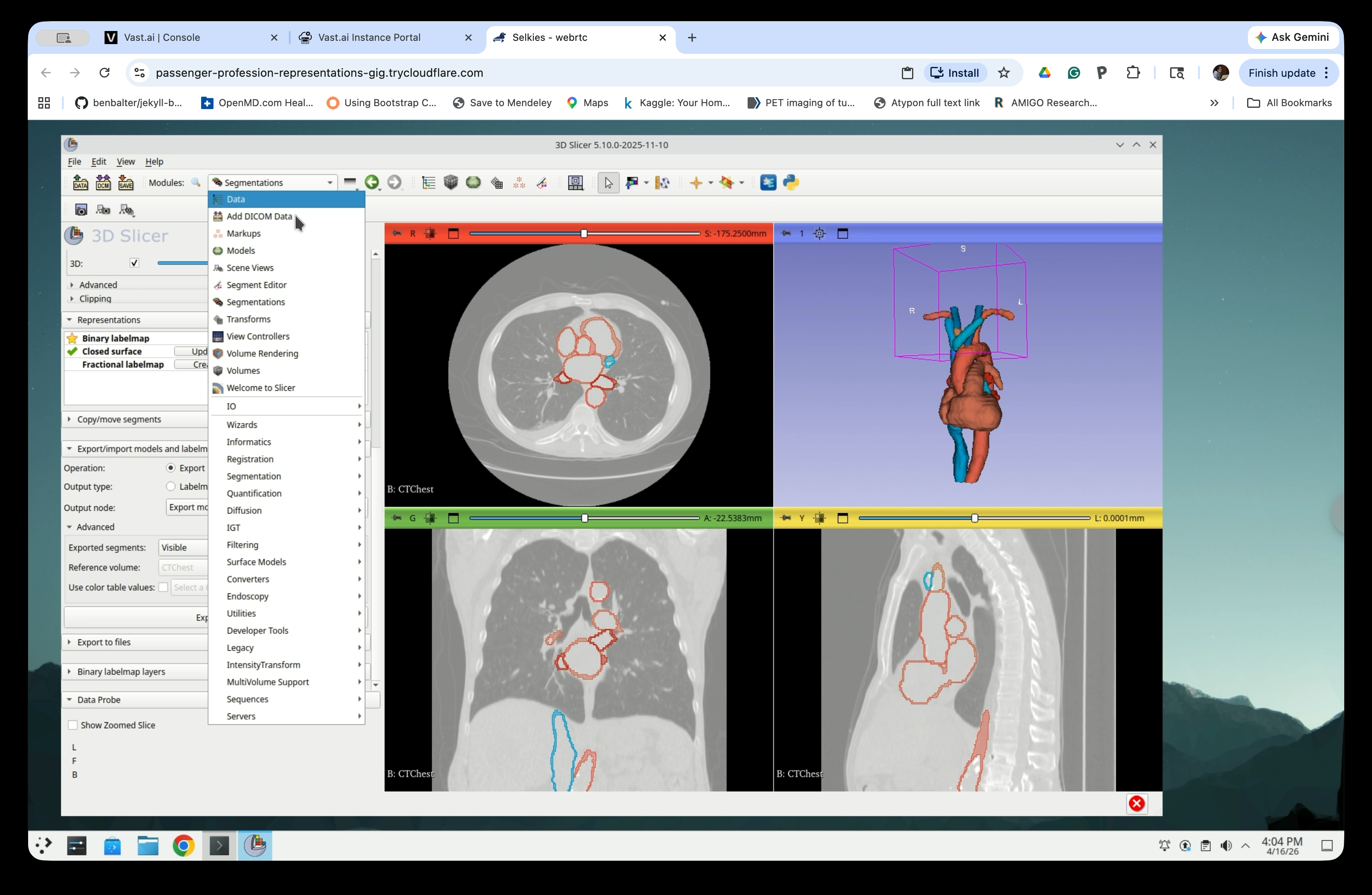
Step 20: Review Hollow Result
The segments will now appear as outlines (hollow shells) in the slice views, and the 3D view will show the thin-shell models.

Part 5: Export Segments as Surface Models
Step 21: Switch to the Segmentations Module
From the Modules menu, navigate to Segmentations.

Step 22: Configure the Export
Scroll down to the Export/Import models and labelmaps section and set:
- Operation: Export
- Output type: Models
- Output node: Export models to new folder

Step 23: Set Exported Segments to Visible
Under Advanced, set Exported segments to Visible so that only the currently visible segments are exported.

Step 24: Run the Export
Click Export. Slicer will create a new folder in the scene containing one model node per segment.

Part 6: Organize the Scene
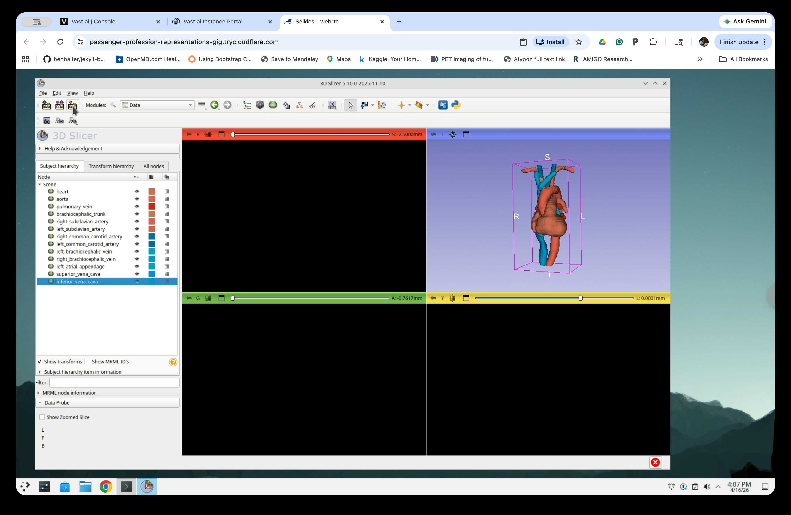
Step 25: Open the Data Module
From the Modules menu, navigate to Data.
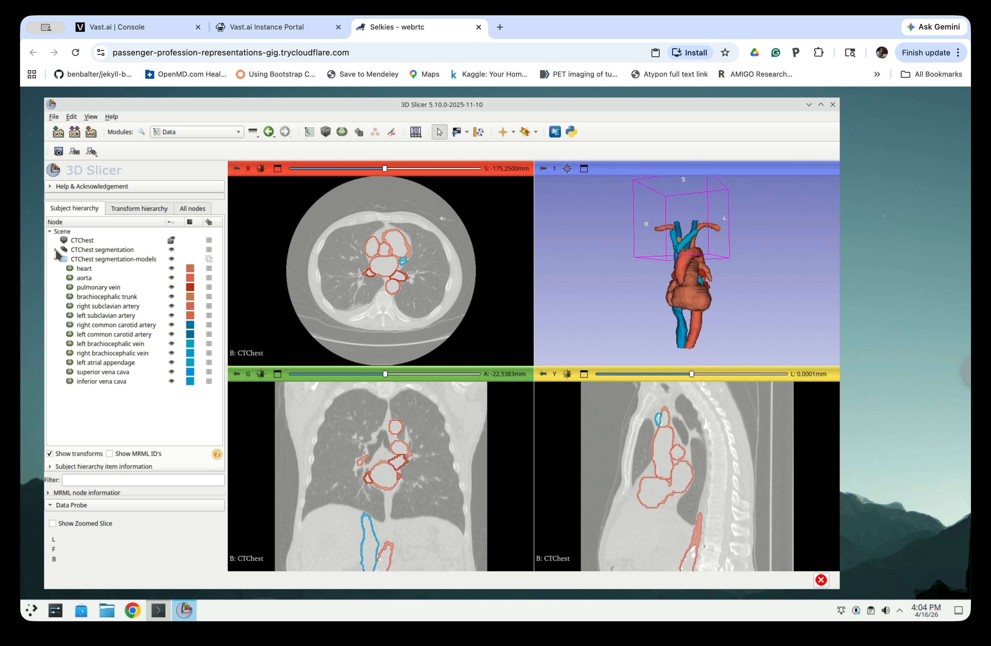
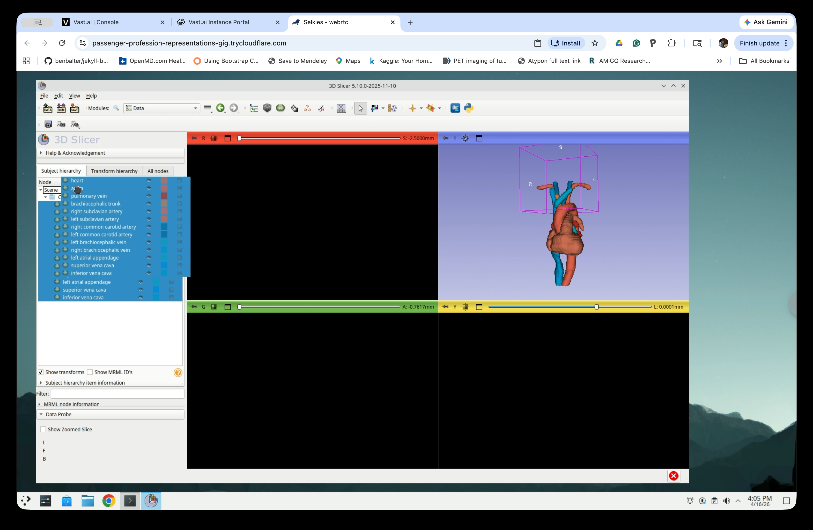
Step 26: Inspect the Scene Tree
The Data module shows the scene hierarchy. You will see:
- The CTChest volume node
- The CTChest segmentation node with all segments
- The CTChest segmentation-models folder containing the exported model nodes
The models folder contains one node per exported segment (heart, aorta, pulmonary vein, etc.).
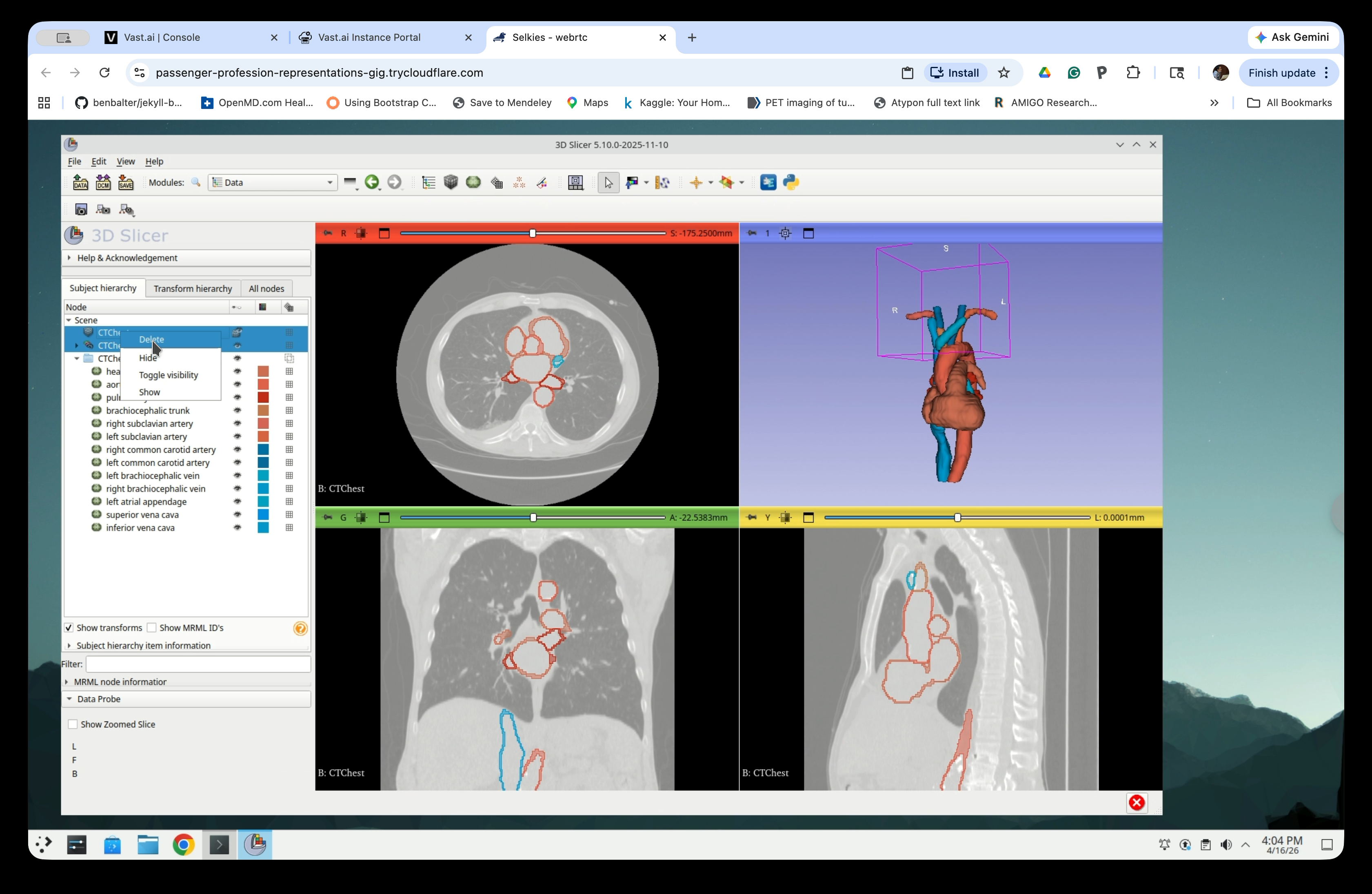
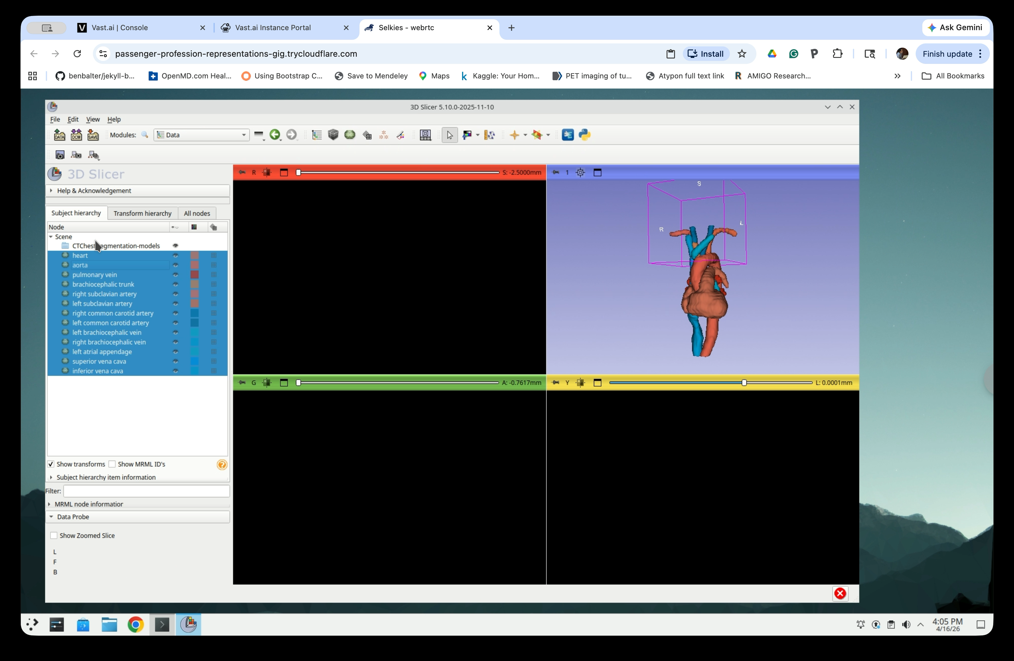
Step 27: Delete the CT Volume and Segmentation Nodes
Right-click the CTChest volume node and CTChest segmentation, and select Delete. Do not delete Chest segmentation-models.
When prompted to delete the subject hierarchy branch, click Yes to All.
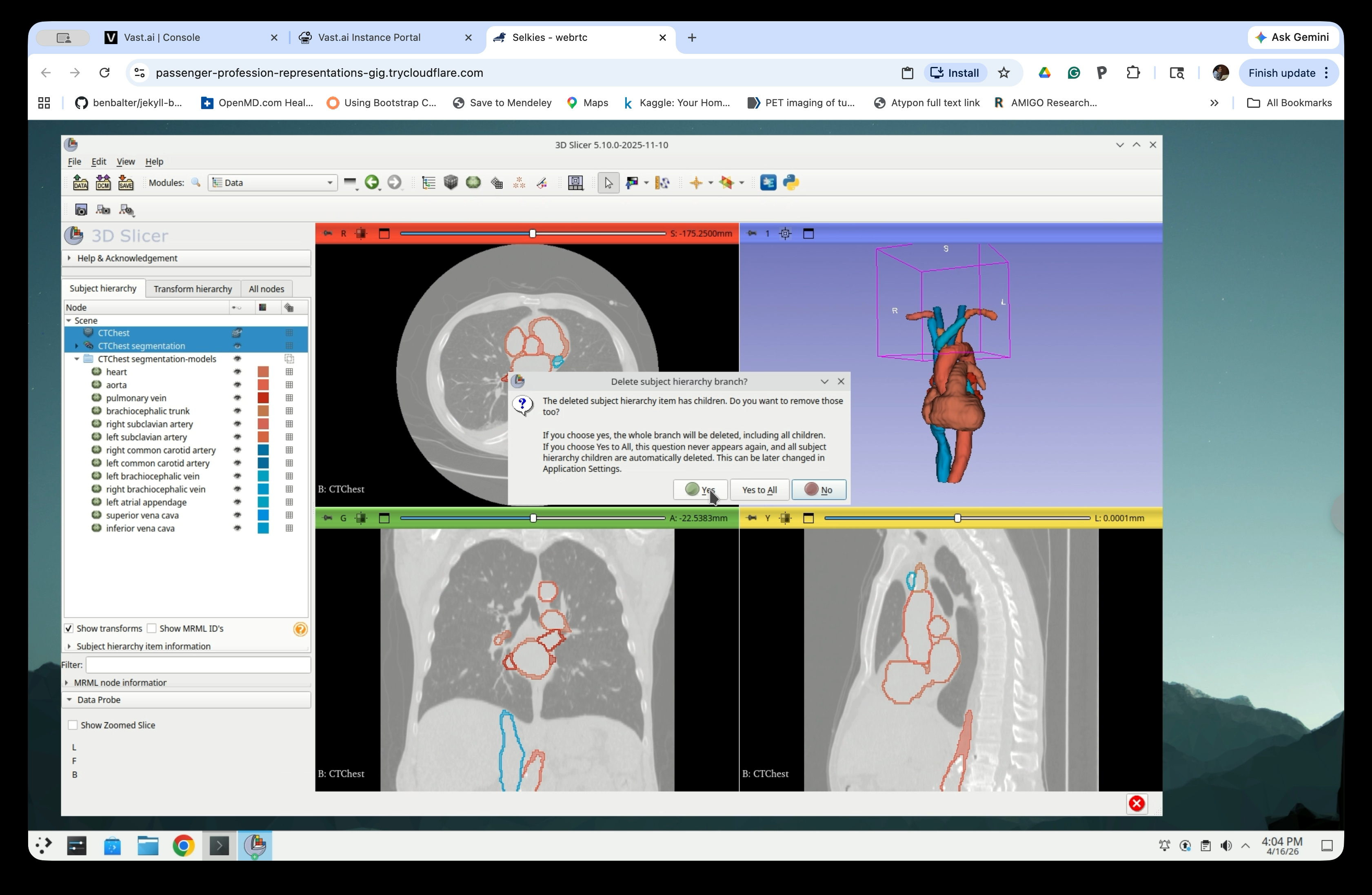
After deletion, only the model nodes remain in the scene.

Step 28: Move Models to the Top Level
Select all model nodes in the scene tree and drag them up to the Scene root level, out of the segmentation-models folder.
After moving, all models are directly under Scene.
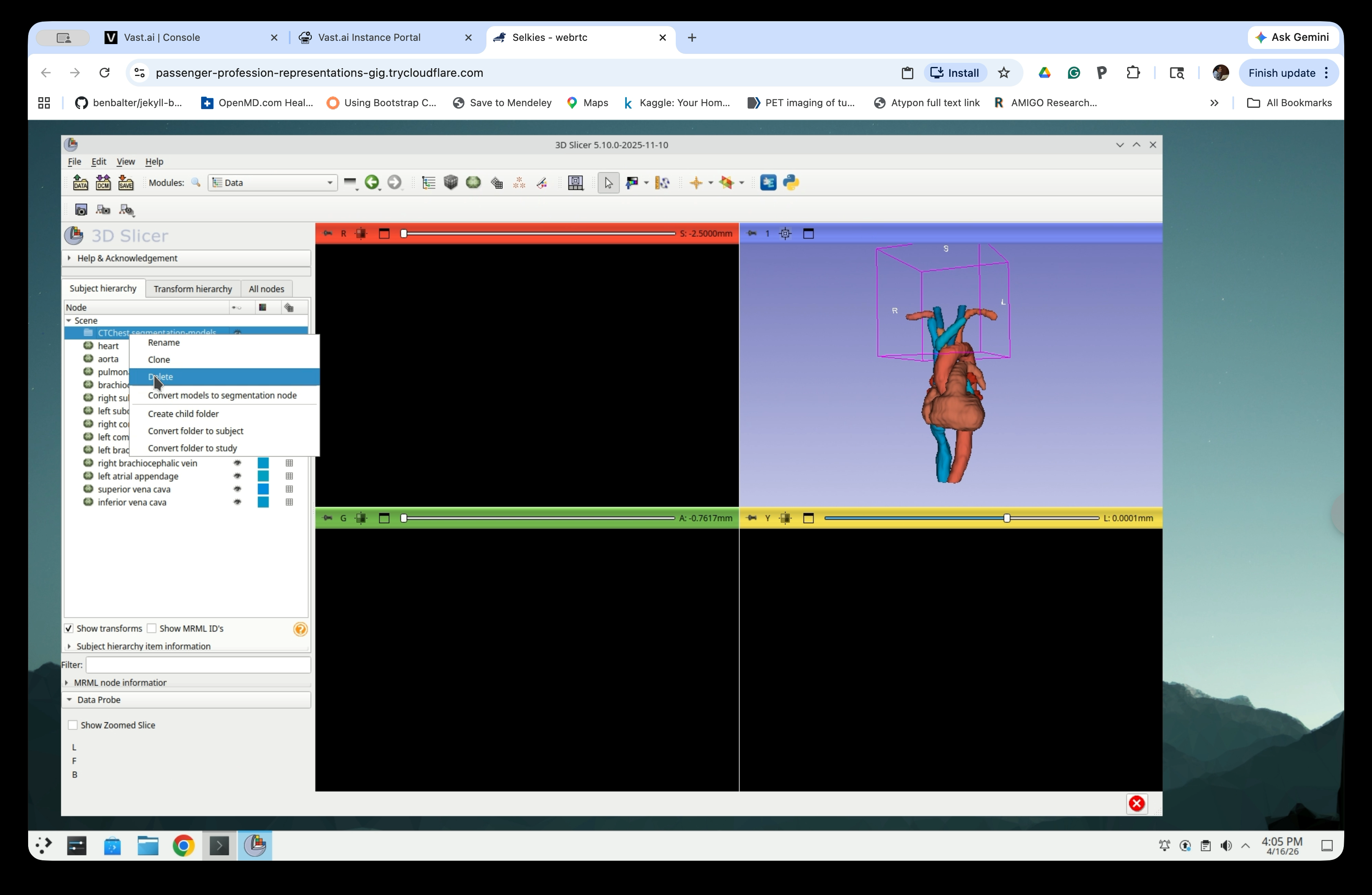
Step 29: Delete the Empty Folder
Right-click the now-empty CTChest segmentation-models folder and select Delete.
Step 30: Rename the Model Nodes
To avoid ‘ ‘ (space) in the file names, replace the all spaces in the node names with ‘_’ (underscore). To do so, right-click each model node and select Rename.
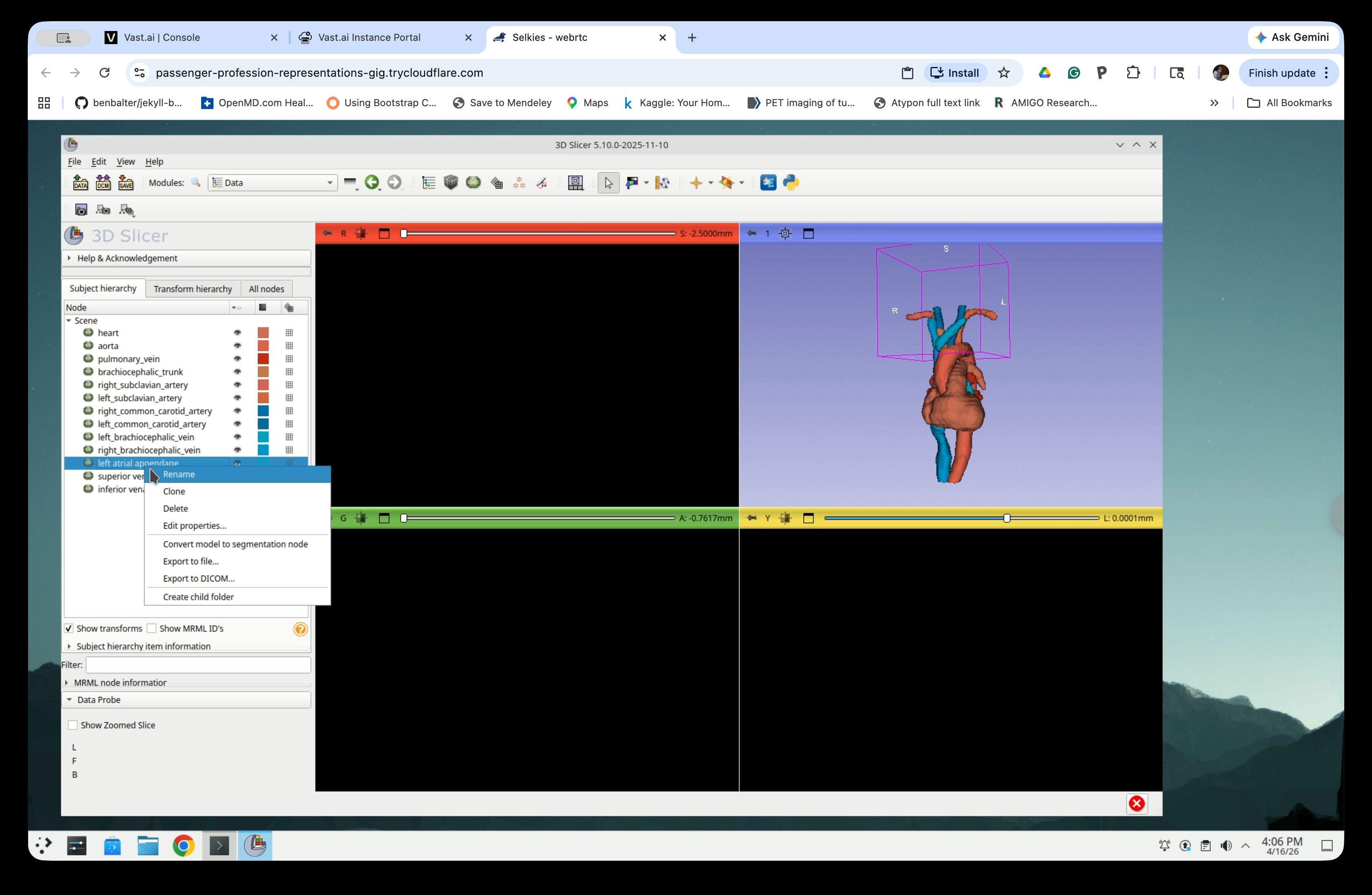
Edit the name to replace the space(s) with underscore(s) in the rename dialog and click OK.

Repeat for each model node with a name that contains any underscore.
Part 7: Save the Slicer scene
Step 31: Open the Save Dialog
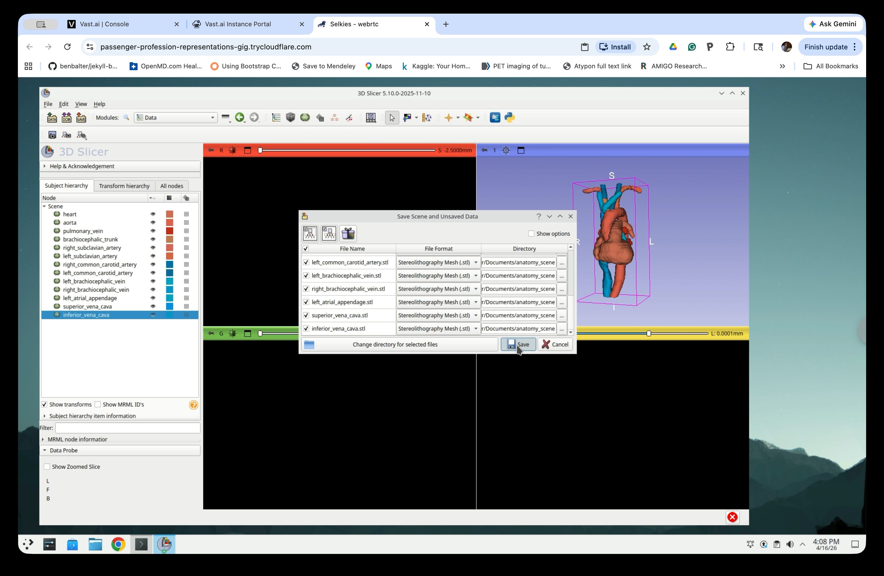
Go to File → Save (or press Ctrl+S) to open the Save Scene and Unsaved Data dialog. The dialog lists all nodes and their current file format.
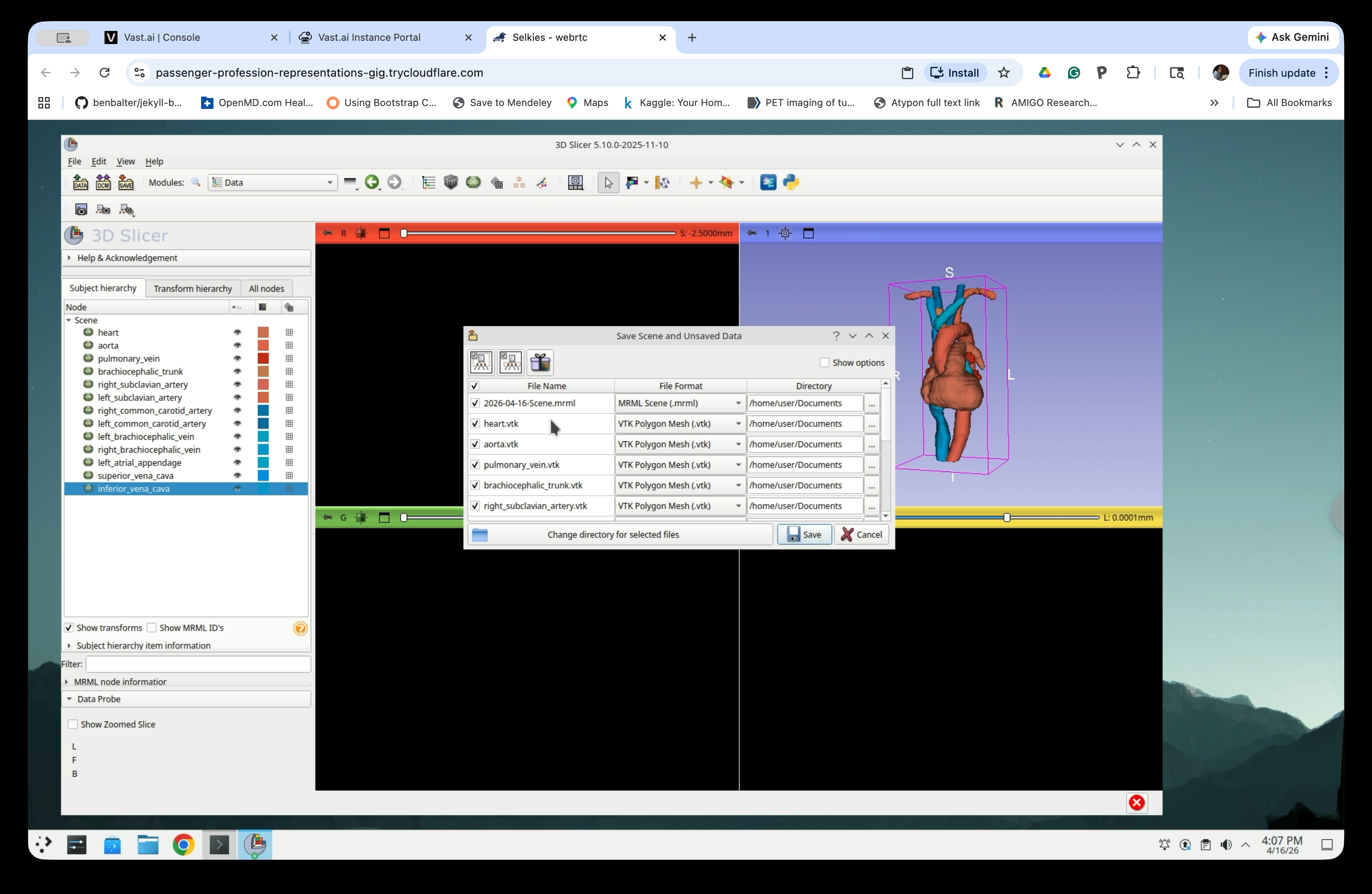
Step 32: Change File Format to STL
For each model node, click the File Format dropdown and select Stereolithography Mesh (.stl).

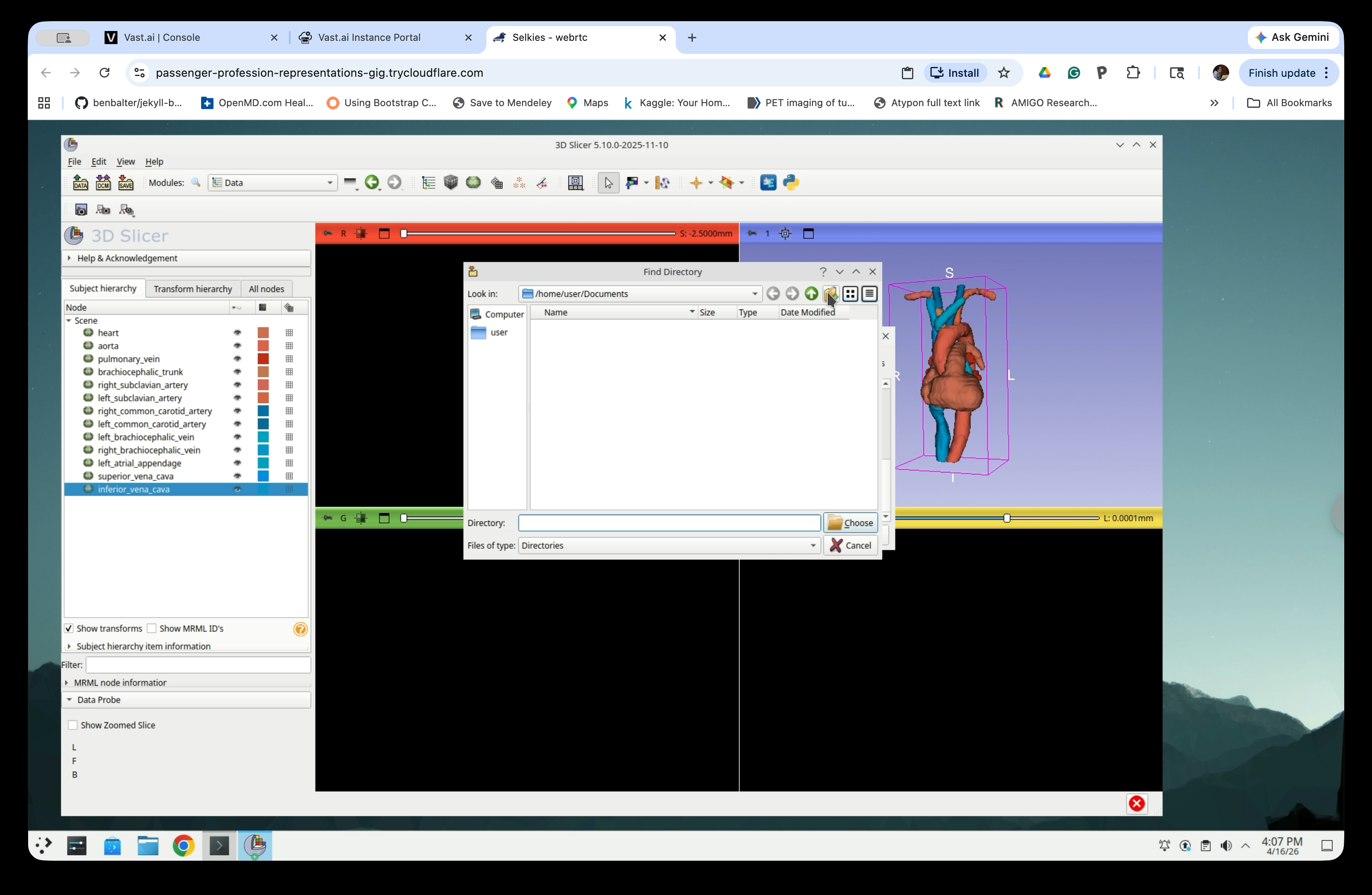
Step 33: Choose a Save Directory
Click Change directory for selected files to open the Find Directory dialog. Navigate to /home/user/Documents.

Step 34: Create a New Folder
Click the New Folder button in the toolbar to create a new folder.
Step 35: Name the Folder
Type a name for the folder (e.g., anatomy_scene) and press Enter.

Confirm the folder name is set correctly.
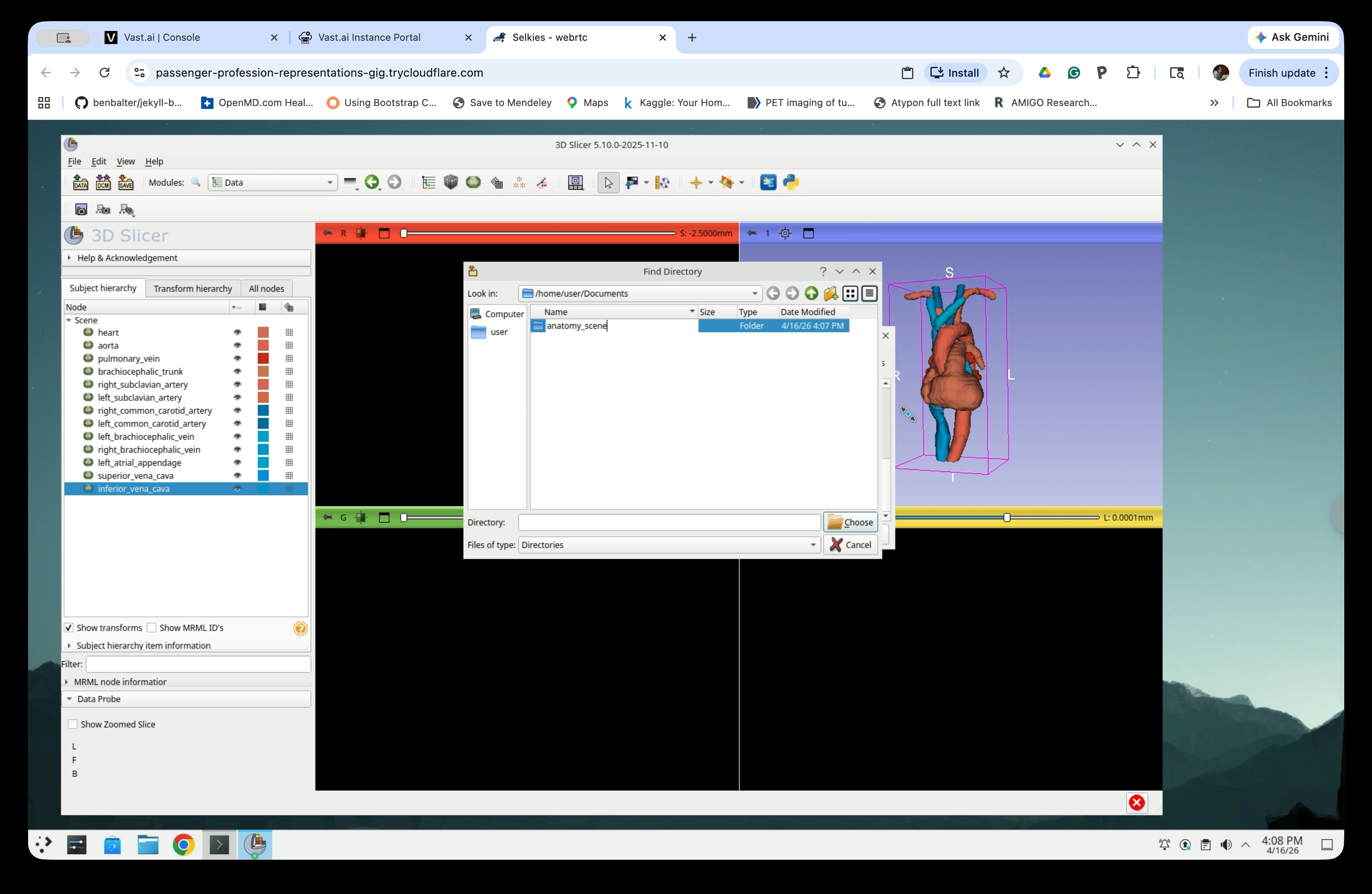
Step 36: Select the Folder
Click the anatomy_scene folder to select it, then click Choose.

Step 37: Save All Files
The save dialog now shows all model files in STL format with the directory set to Documents/anatomy_scene. Click Save to write all files.
The STL files are now saved to ~/Documents/anatomy_scene/ and are ready to be loaded into SlicerROS2.