Follow-along: Building a navigation-ready surgical scene
Tutorial Part 1: Building a navigation ready surgical scene
In this interactive session, you will build a complete image-guided navigation scene in 3D Slicer: load and segment a CT image of a spine phantom, pivot-calibrate a tracked needle, register the patient anatomy to an optical tracker, and finally load a Micromate robot through SlicerROS2 and register it into the same coordinate frame.
The session is presented in two parts — Building a navigation-ready surgical scene (Laura Connolly, PhD) and Loading and registering the robot to the patient (Michelle Song, PhD Student).
Prerequisites: Complete the environment setup in the Prerequisites page and launch a vast.ai container as described in Launching a Container on Vast.ai. All commands below are run inside Konsole terminals in the vast.ai desktop environment, and all data files are located in /home/user/workshop_data/.
Part 1: Getting Started with 3D Slicer
Step 1: Open a Konsole Terminal
From the vast.ai desktop, open the applications menu and launch Konsole. This is the terminal you will use to launch Slicer.
Step 2: Navigate to the ROS 2 Workspace
In the terminal, move from the default /workspace directory into the ROS 2 workspace:
cd ../
cd home/user/ros2_ws
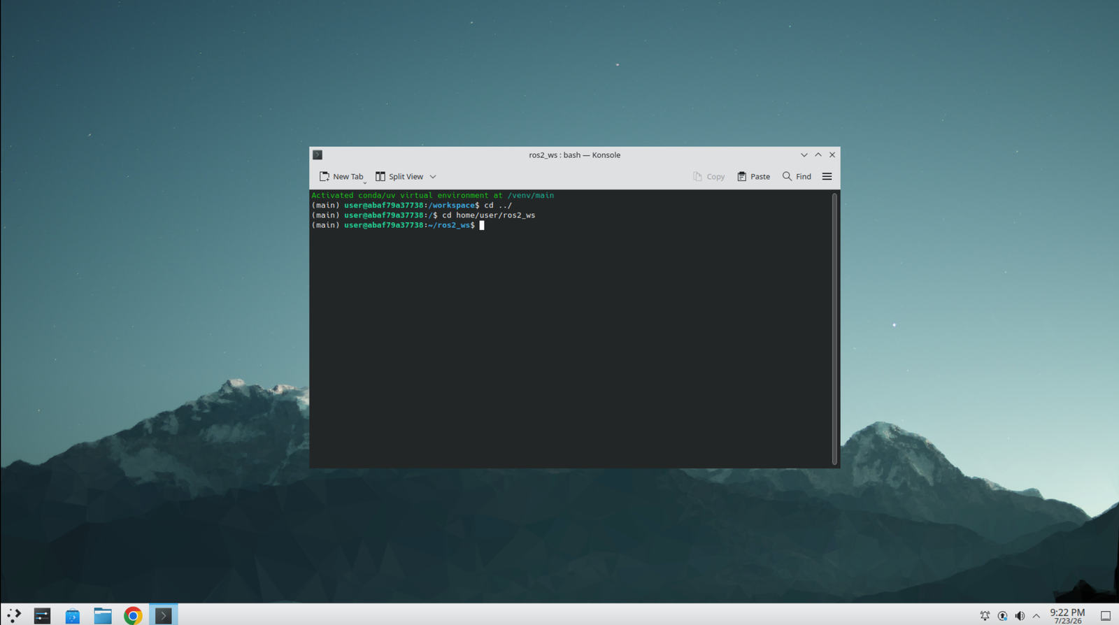
Step 3: Launch 3D Slicer
Source the workspace overlay and start Slicer with the SlicerROS2 module:
source install/setup.bash
ros2 run slicer_ros2_module slicer
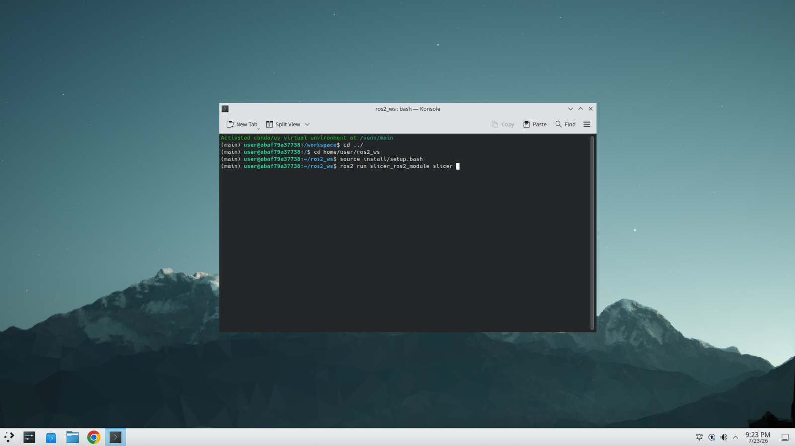
Step 4: Make Slicer Full-Screen
Once the Slicer window appears, maximize it so the full interface is visible.
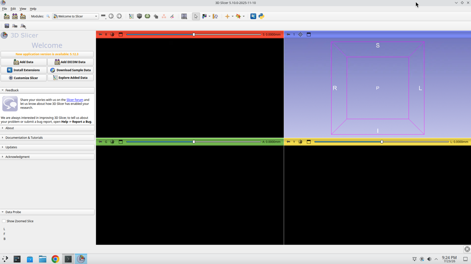
Step 5: Switch the Layout
The default layout is Four-Up. Use the layout selector in the toolbar to try 3D only, then switch back to Four-Up.
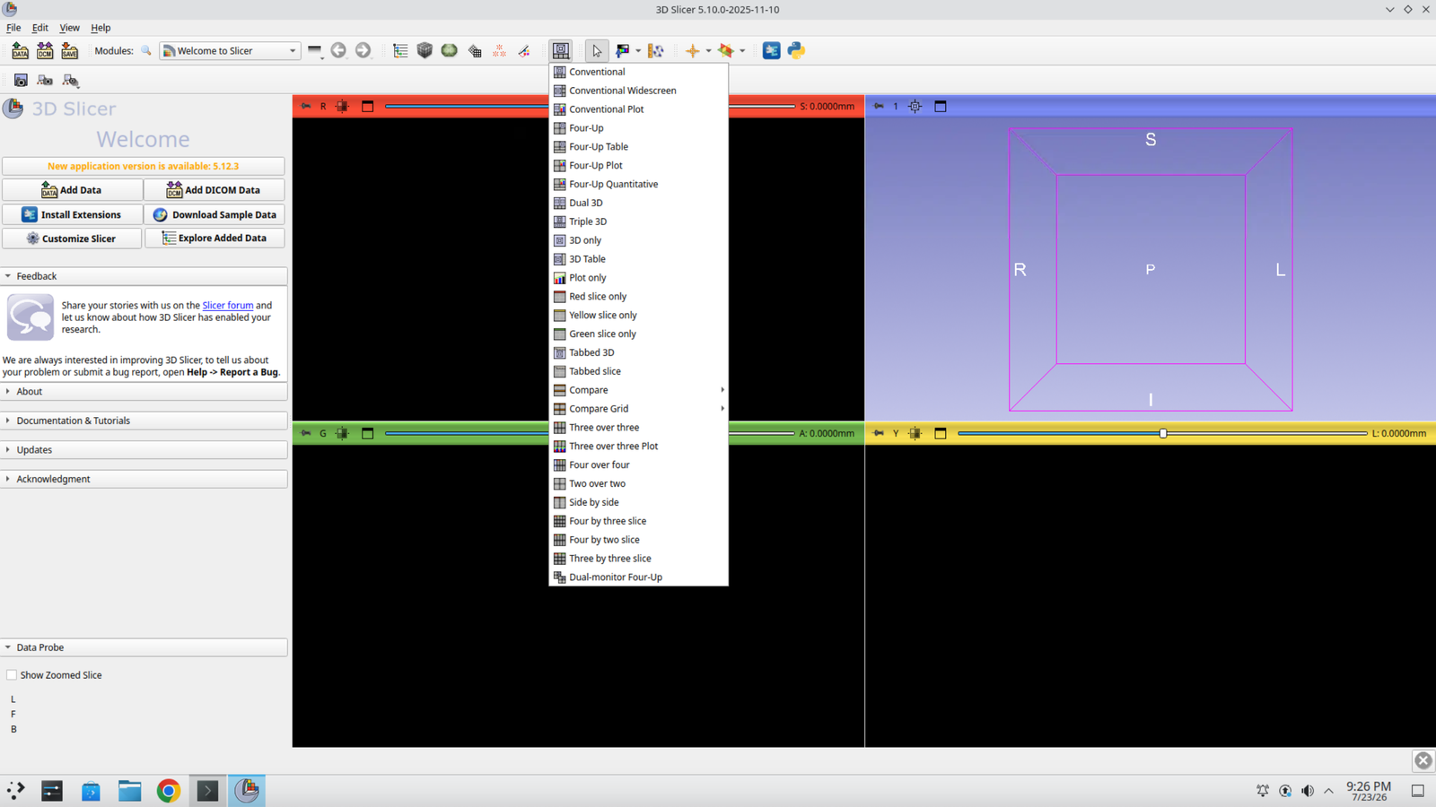
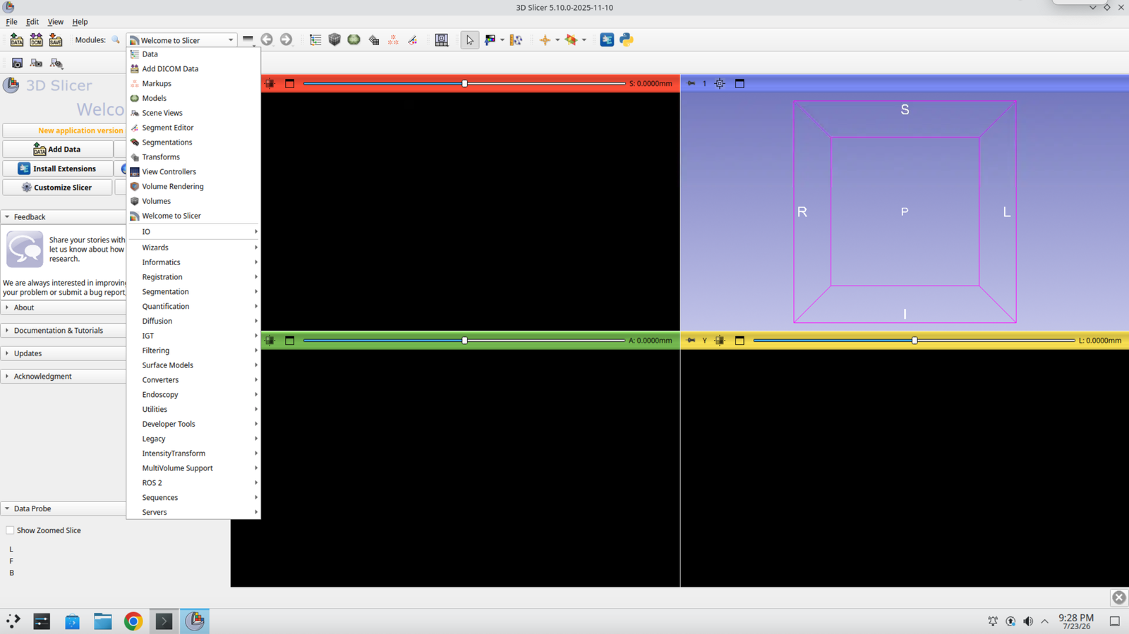
Step 6: Find the Module Selector
The module drop-down in the toolbar is how you switch between the different Slicer modules used throughout this tutorial.
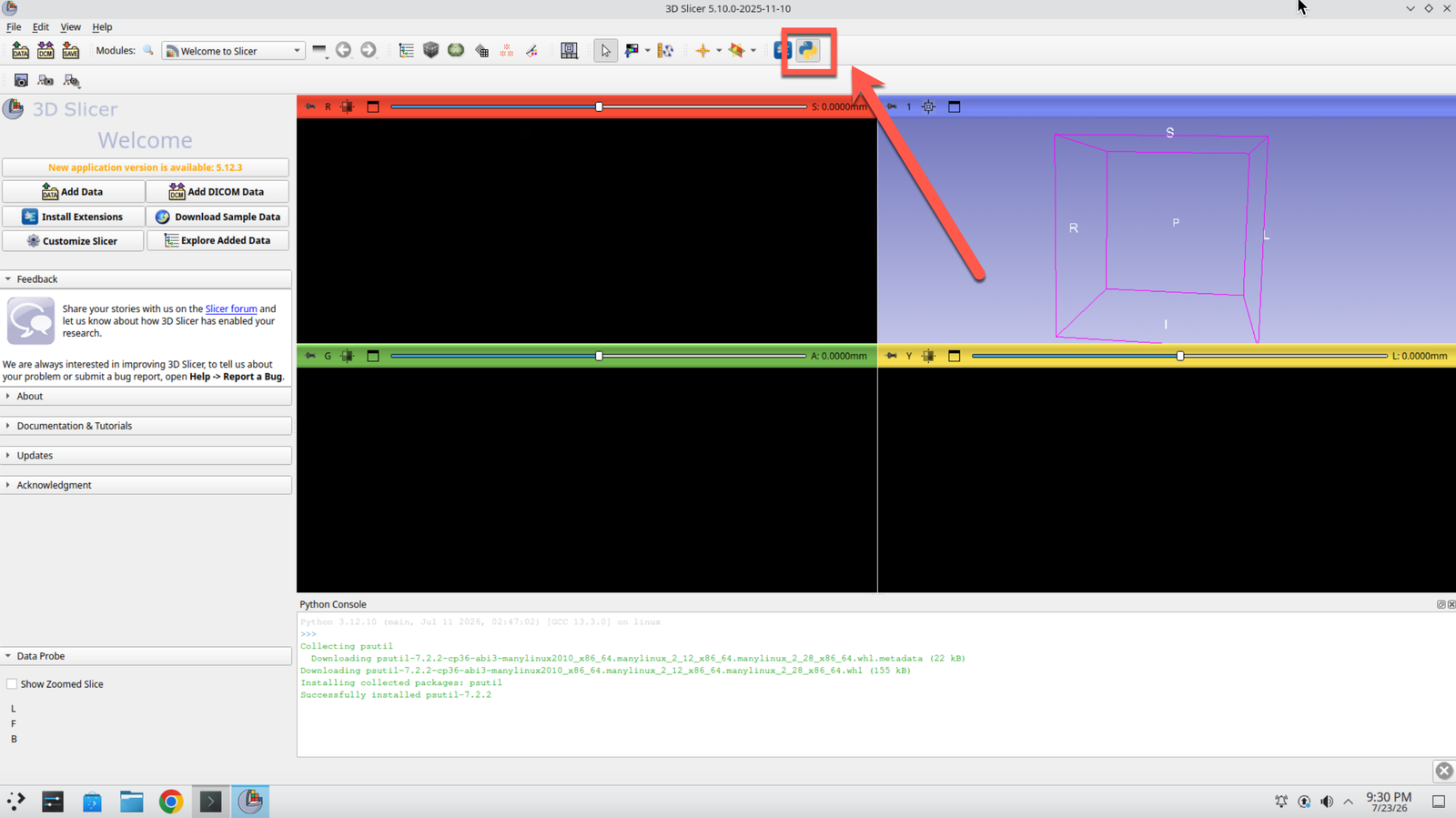
Step 7: Open the Python Console
Open the Python console. This is how you can run code directly inside 3D Slicer.
Part 2: Load and Segment the Medical Image
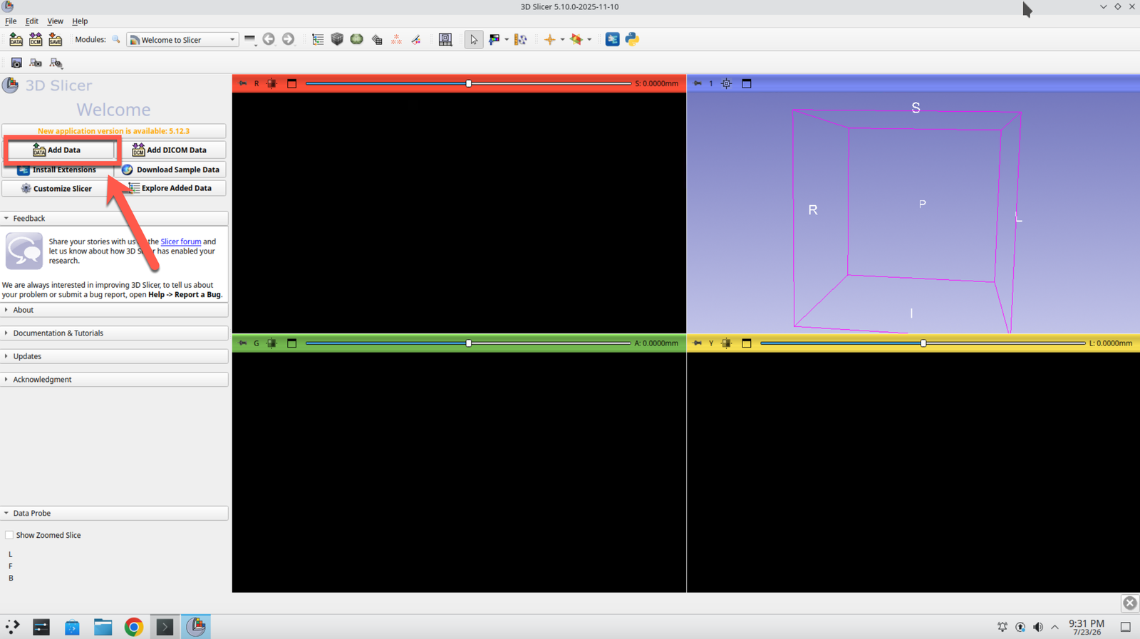
Step 8: Open the Add Data Dialog
Close the Python console, then click the Add Data button in the toolbar.
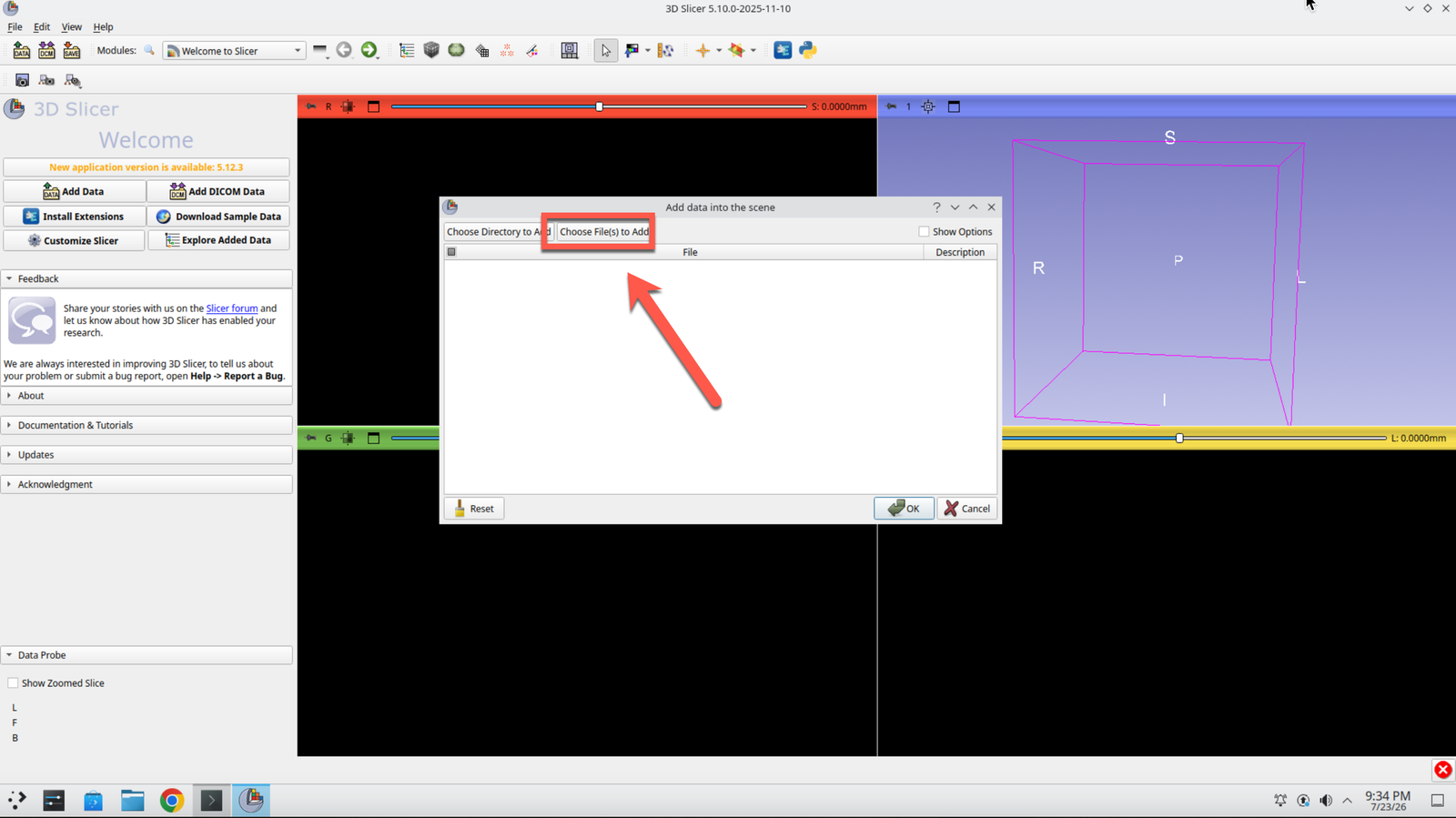
Step 9: Choose Files to Add
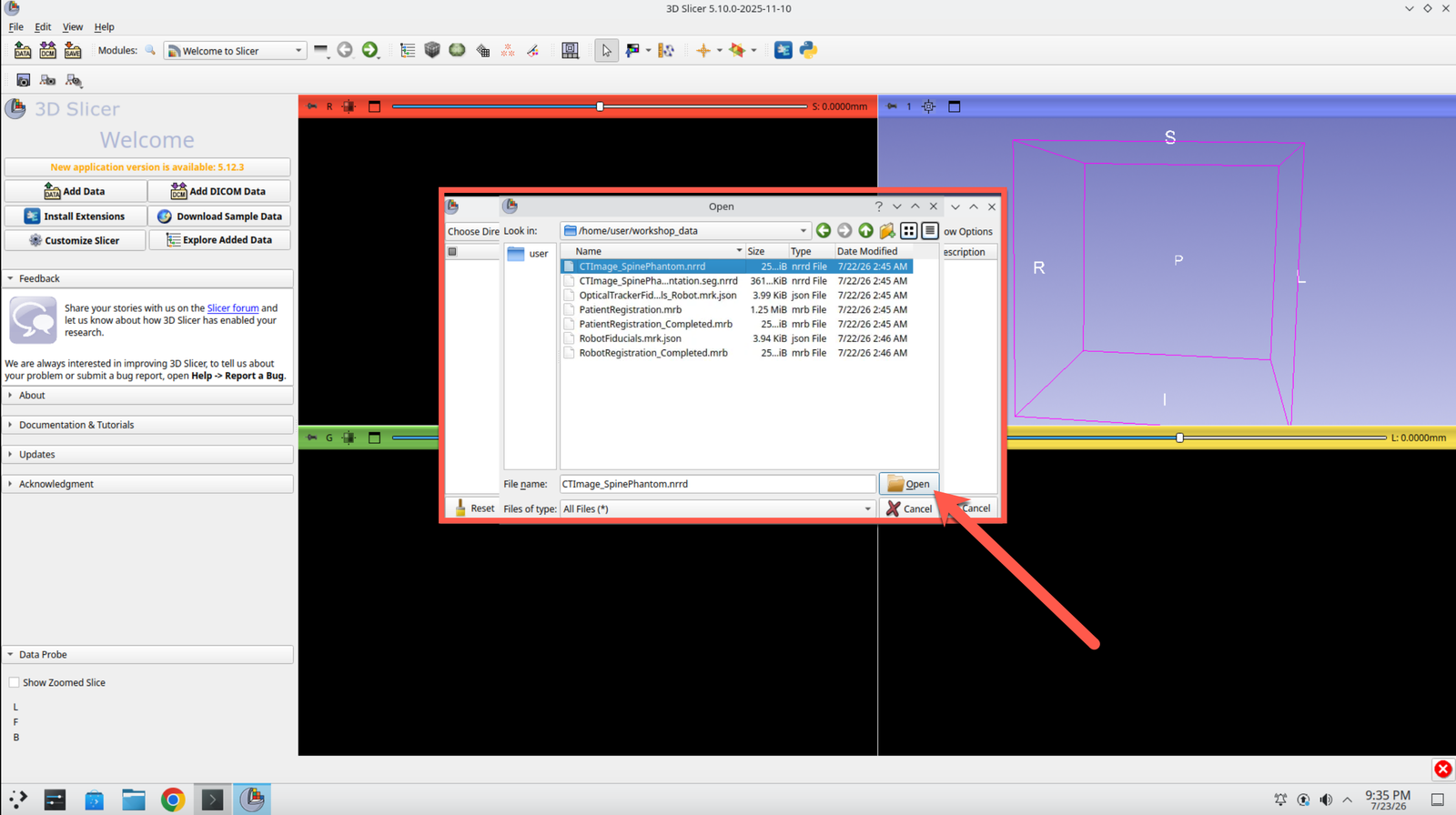
In the Add Data dialog, click Choose File(s) to Add.
Step 10: Select the CT Image
Navigate to /home/user/workshop_data/ and select CTImage_SpinePhantom.nrrd.
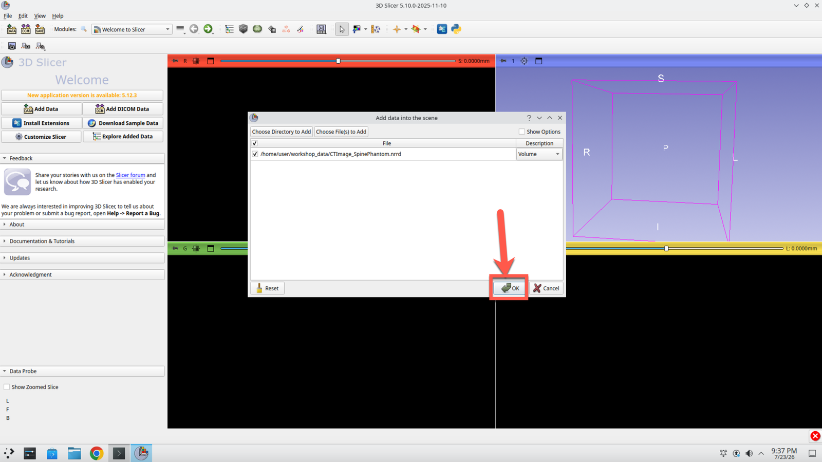
Step 11: Confirm the Load
Click OK to load the image into the scene.
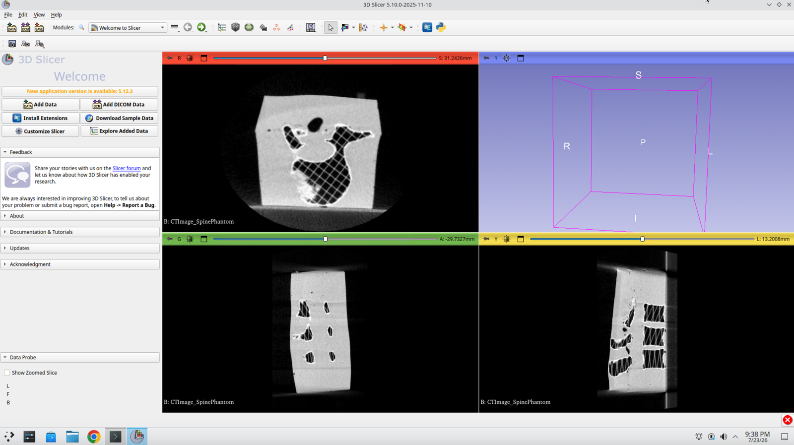
Step 12: Confirm the CT Image Appears
You should now see a CT image of the spine phantom in the slice views.
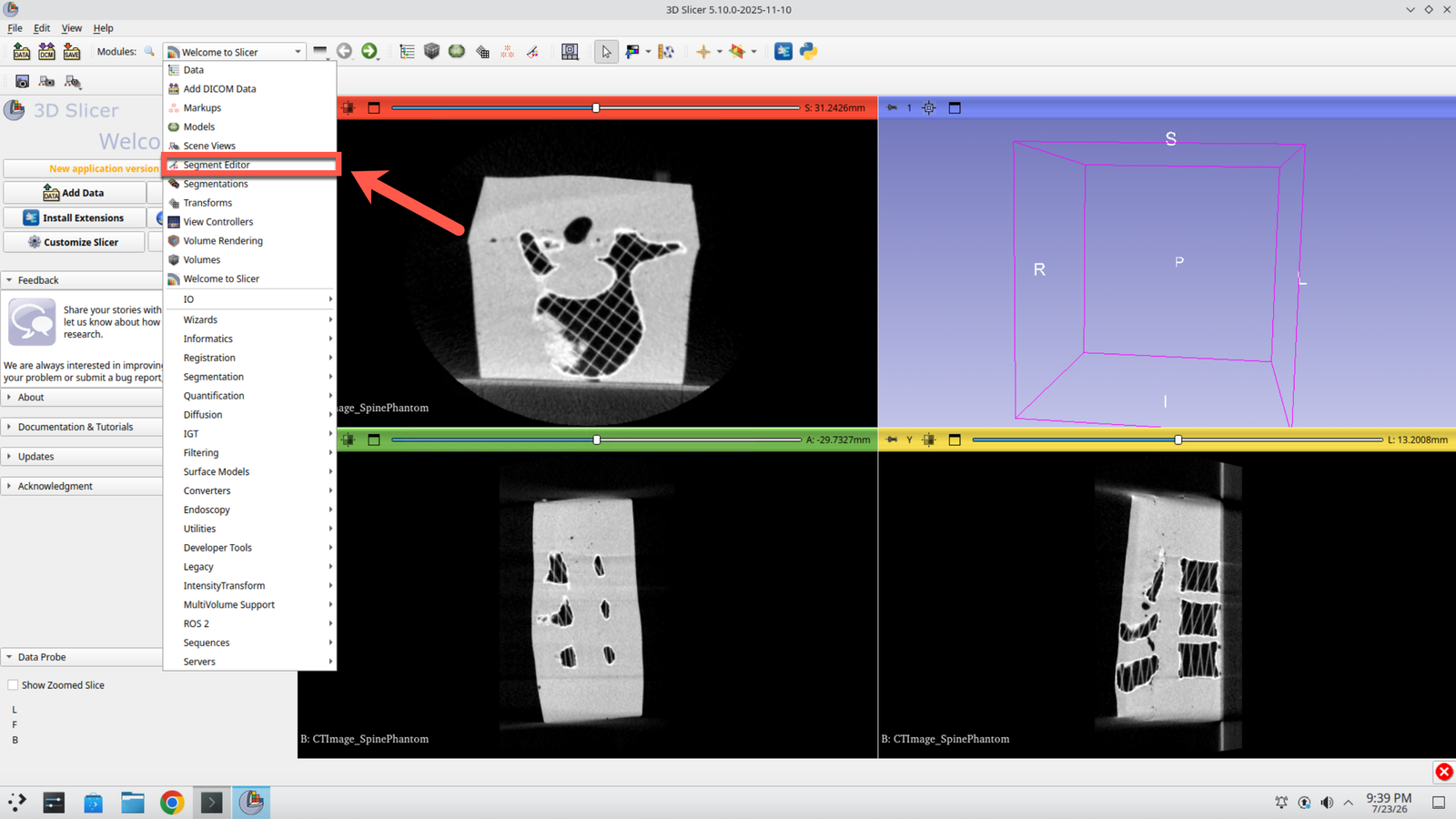
Step 13: Open the Segment Editor
Switch to the Segment Editor module.
Step 14: Create Two Segments
Press Add twice to create two segmentations — one for the background and one for the bone.
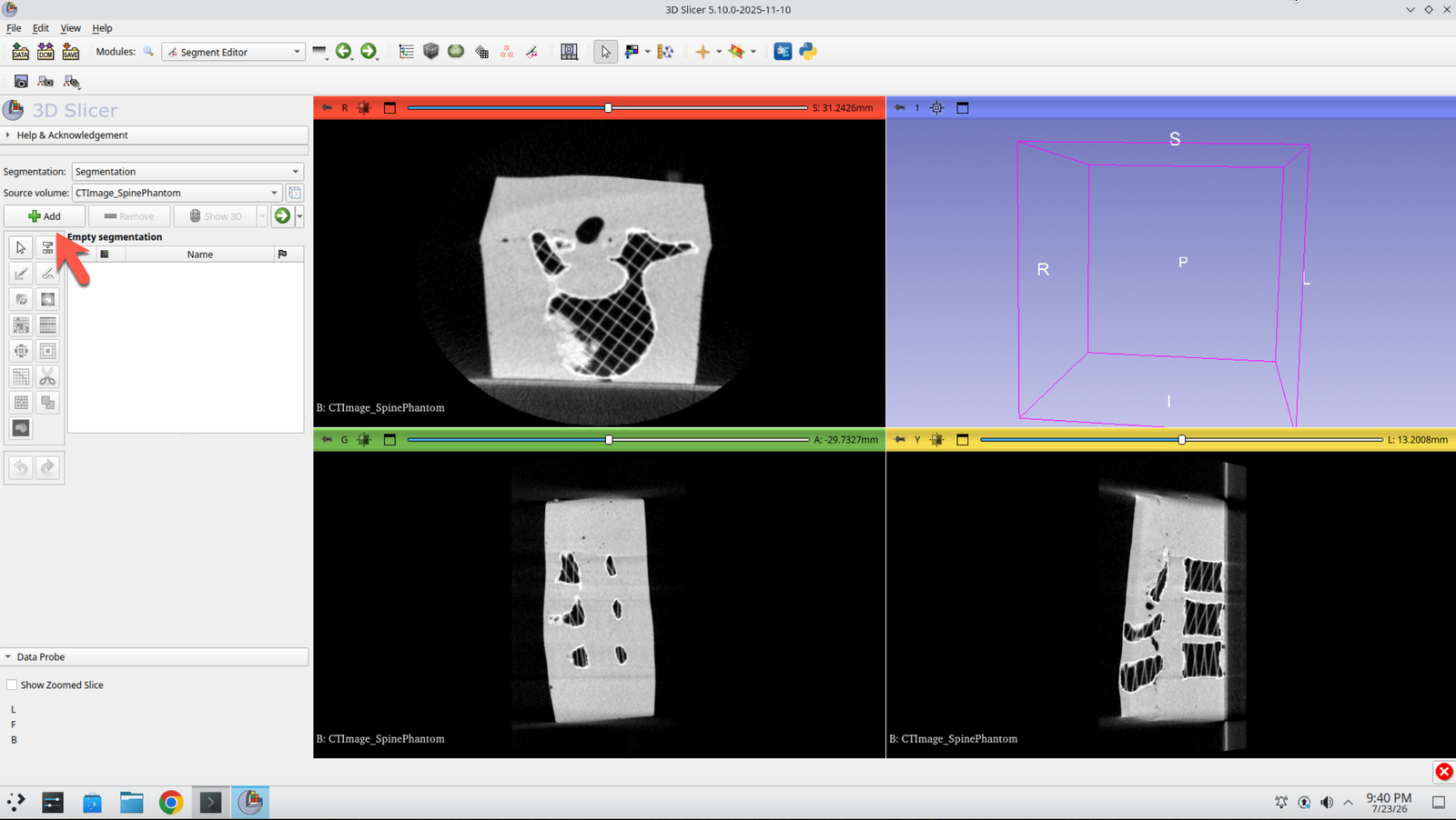
Step 15: Select the Paint Tool
Select the paint brush icon from the effects row.
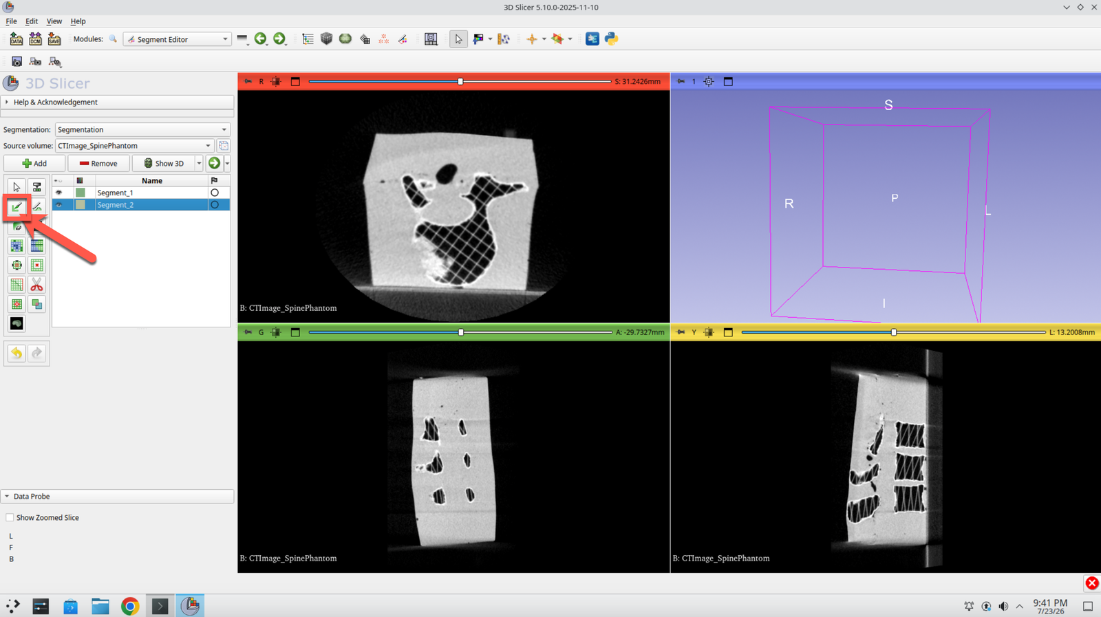
Step 16: Set the Brush Diameter
Change the diameter of the brush to 1% so you can place fine seed strokes.
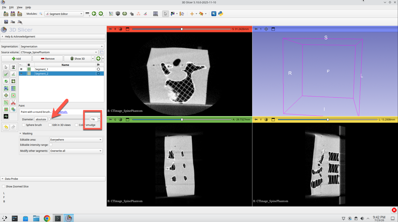
Step 17: Paint the Seeds
Paint on the slices to seed both segments: yellow on the outside (background), green in the bone regions.
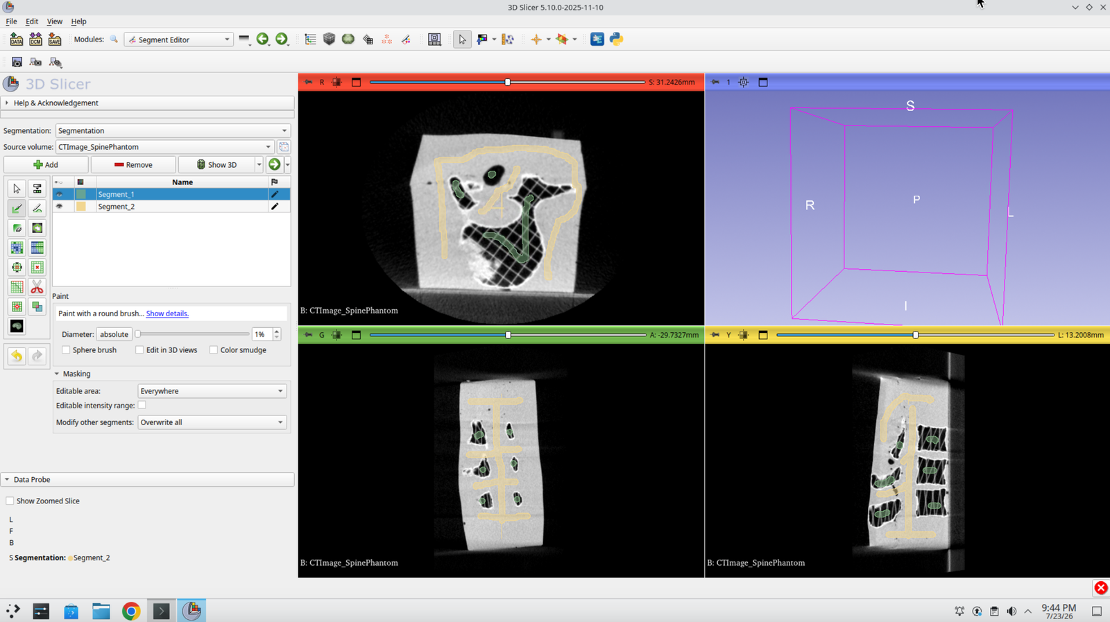
Step 18: Initialize Grow from Seeds
Select the Grow from seeds effect and press Initialize. This may take a second.
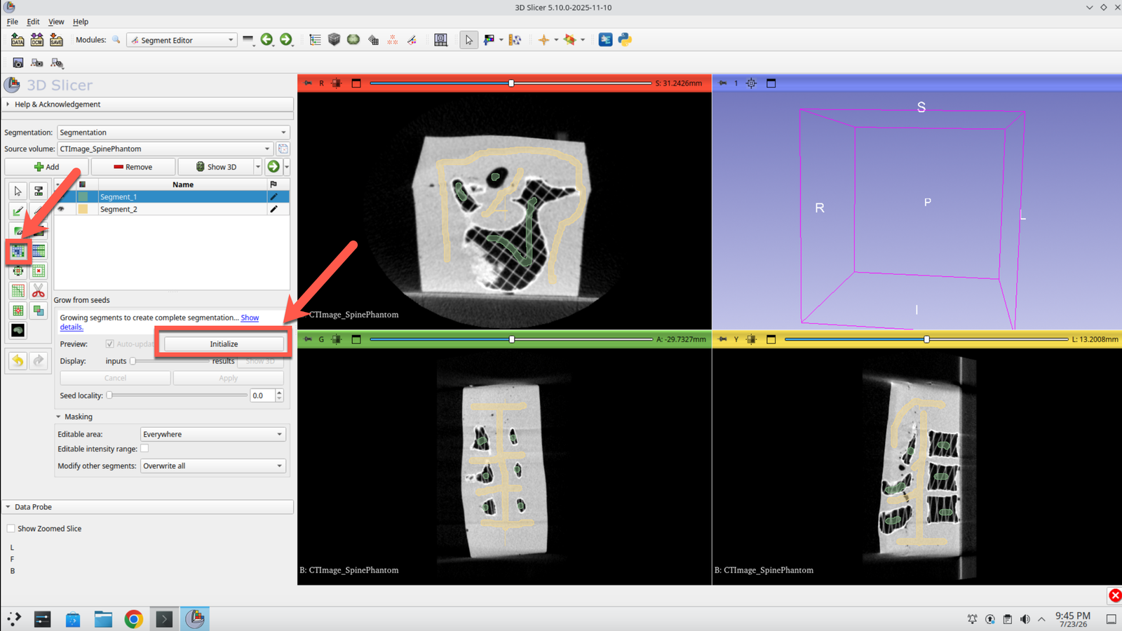
Step 19: Apply the Segmentation
When it finishes, select Apply to commit the grown segmentation.
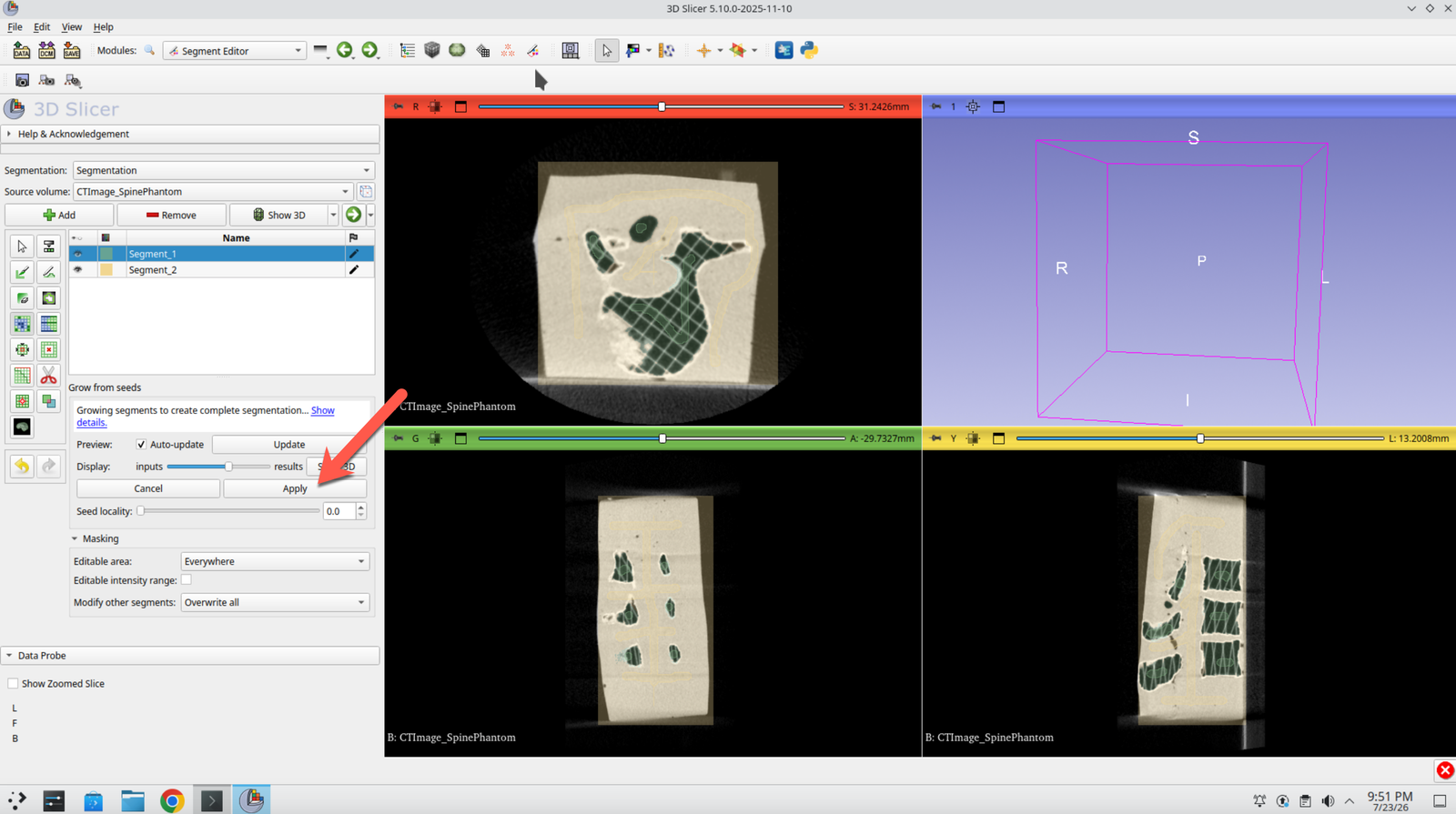
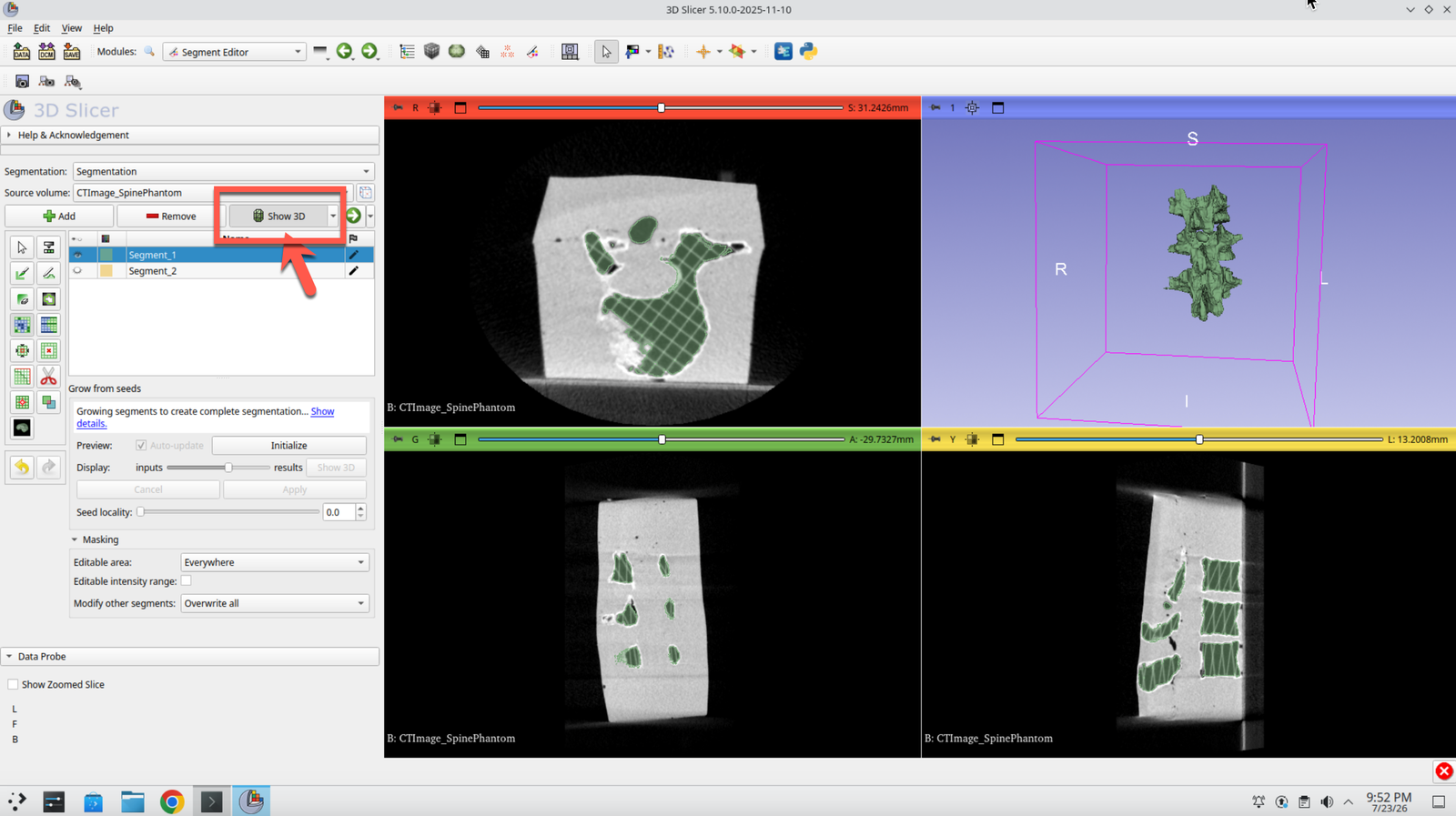
Step 20: Show the Segmentation in 3D
Select Show 3D to render the segmented spine in the 3D view.
Part 3: Register the Patient to the Optical Tracker
Step 21: Open the Data Module
Select the Data button in the top left to load in the pre-recorded tracking data.
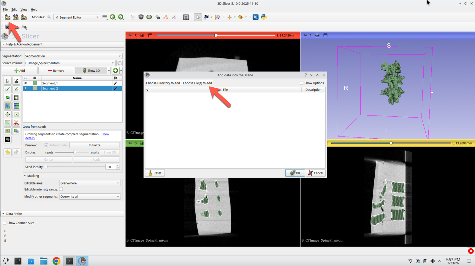
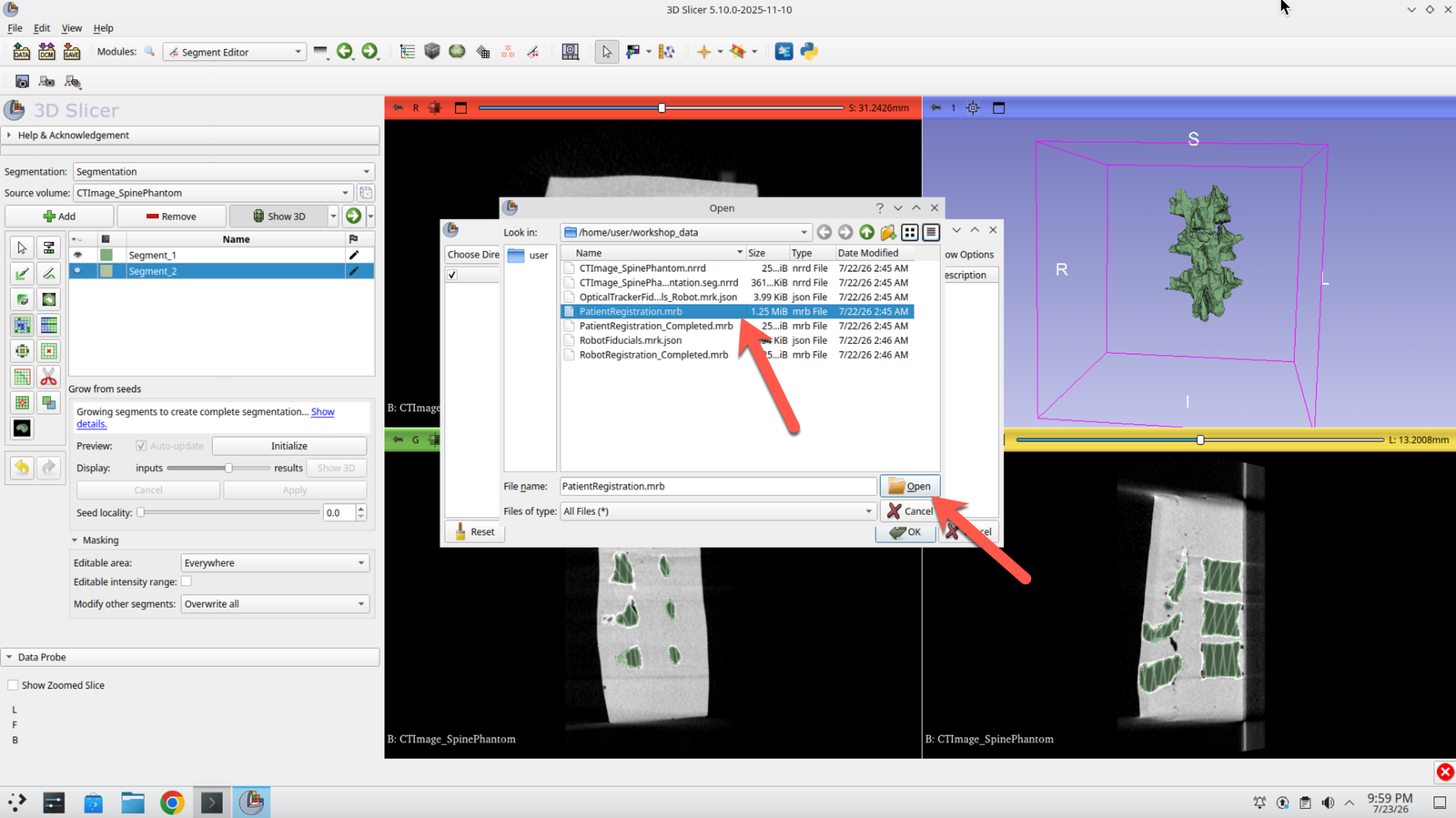
Step 22: Load the Patient Registration Scene
Select the file called PatientRegistration.mrb, click Open, then press OK.
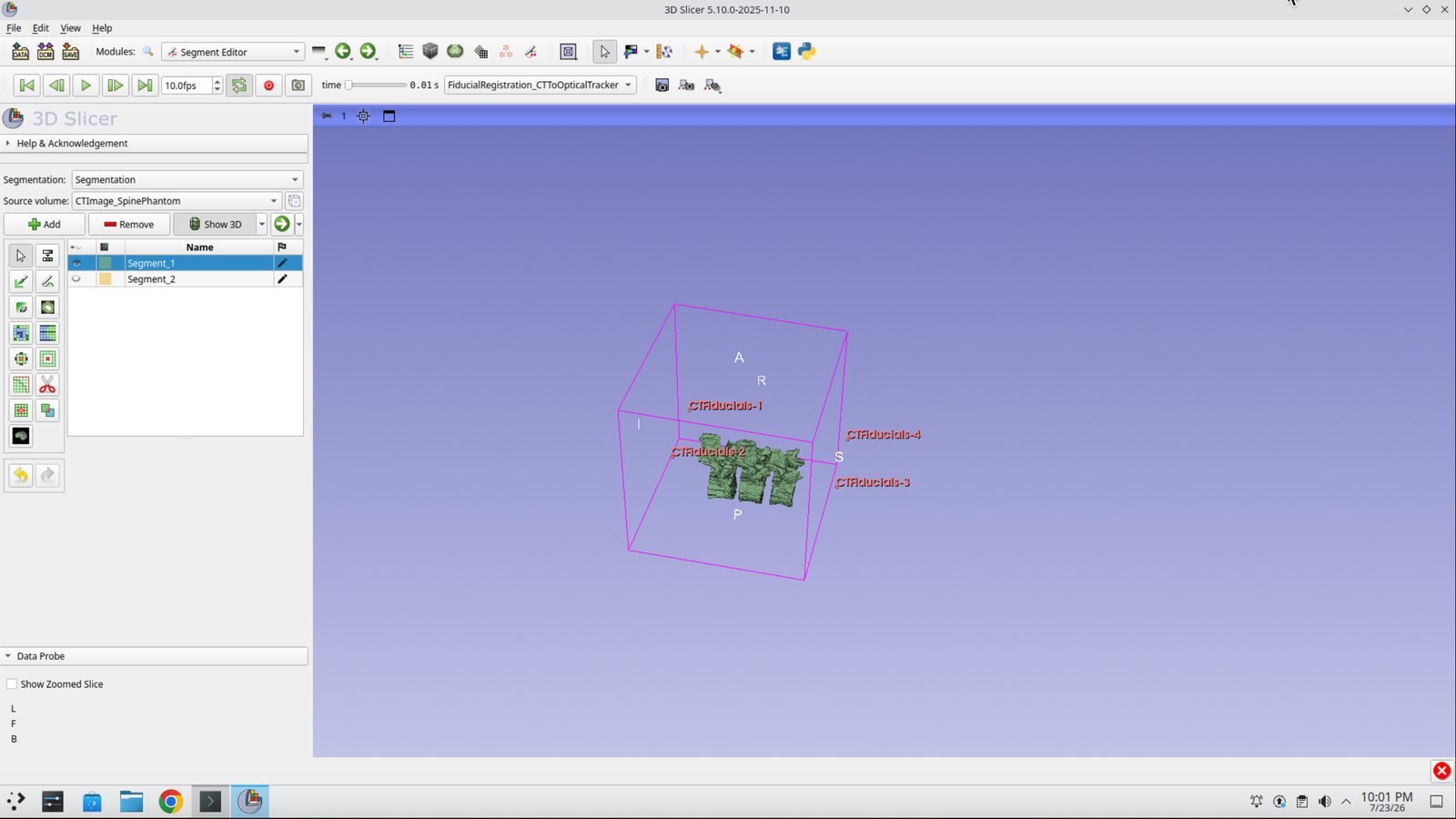
Step 23: Confirm the Scene Loads
You should see the spine and four points around it. These are the corners of the gel block.
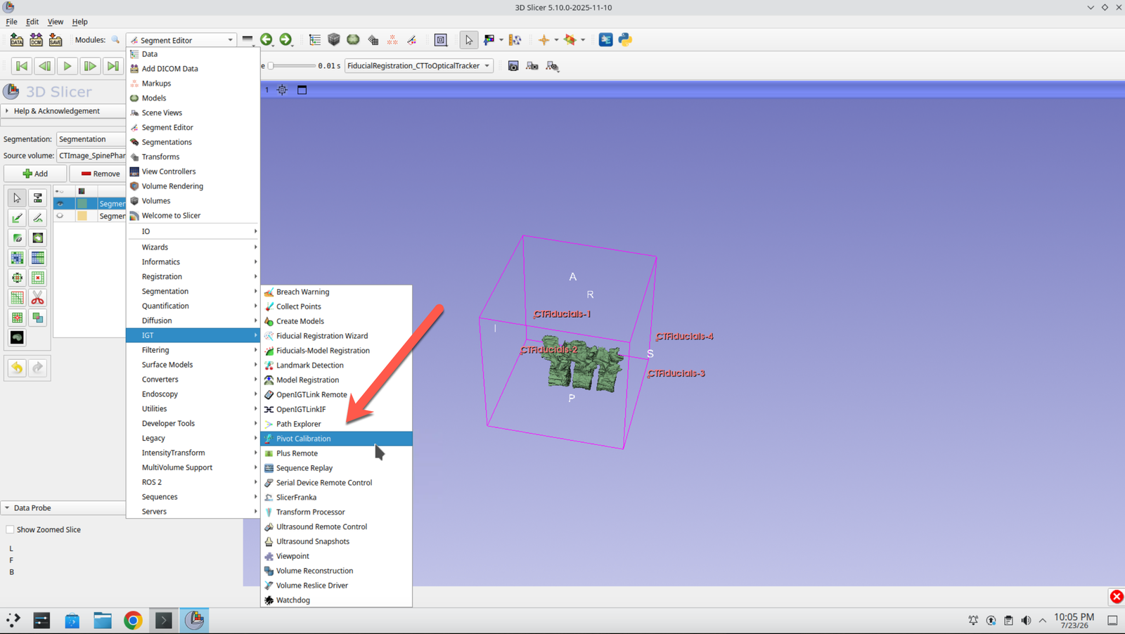
Step 24: Open the Pivot Calibration Module
Switch to the Pivot Calibration module.
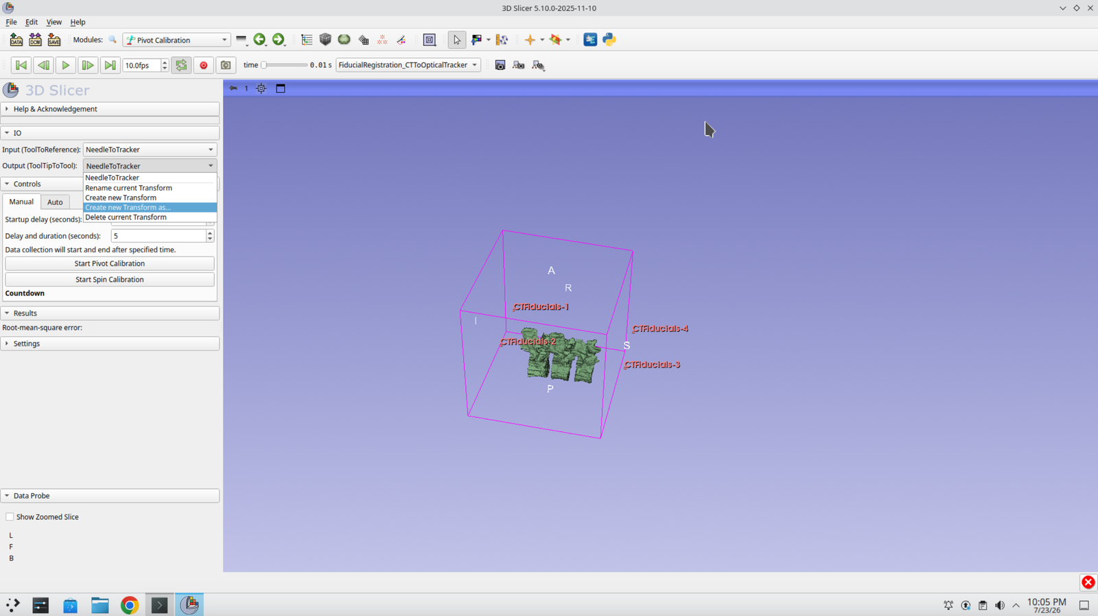
Step 25: Create the Output Transform
Under the Output tab, select Create new transform as….
Step 26: Name the Transform
Name the new transform NeedleTipToNeedle.
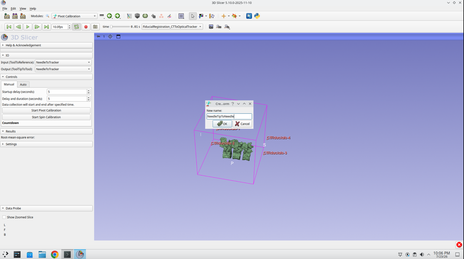
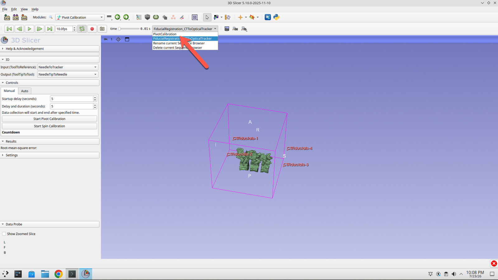
Step 27: Select the Pivot Calibration Sequence
On the sequence toolbar at the top, change the current sequence to PivotCalibration.
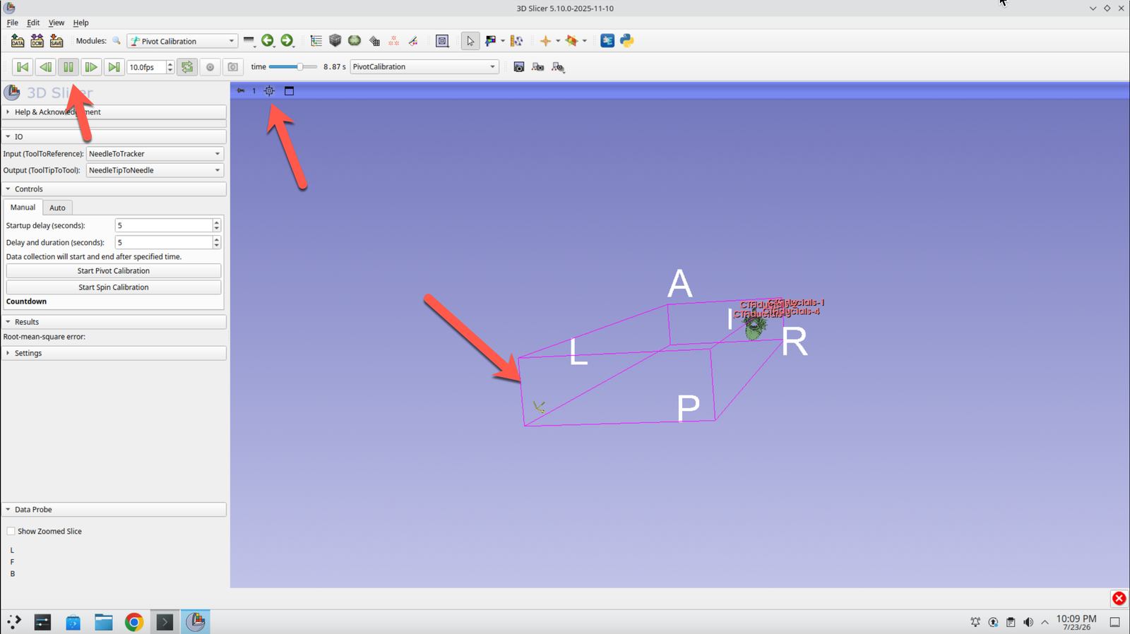
Step 28: Play the Sequence
Press the Play button in the top left and the crosshair button in the 3D viewer. You should see the tracked needle moving through its pivot motion.
Step 29: Run the Pivot Calibration
Press Play and then Start Pivot Calibration. You may need to slow the playback speed to 5.0 fps so the calibration captures enough of the motion.
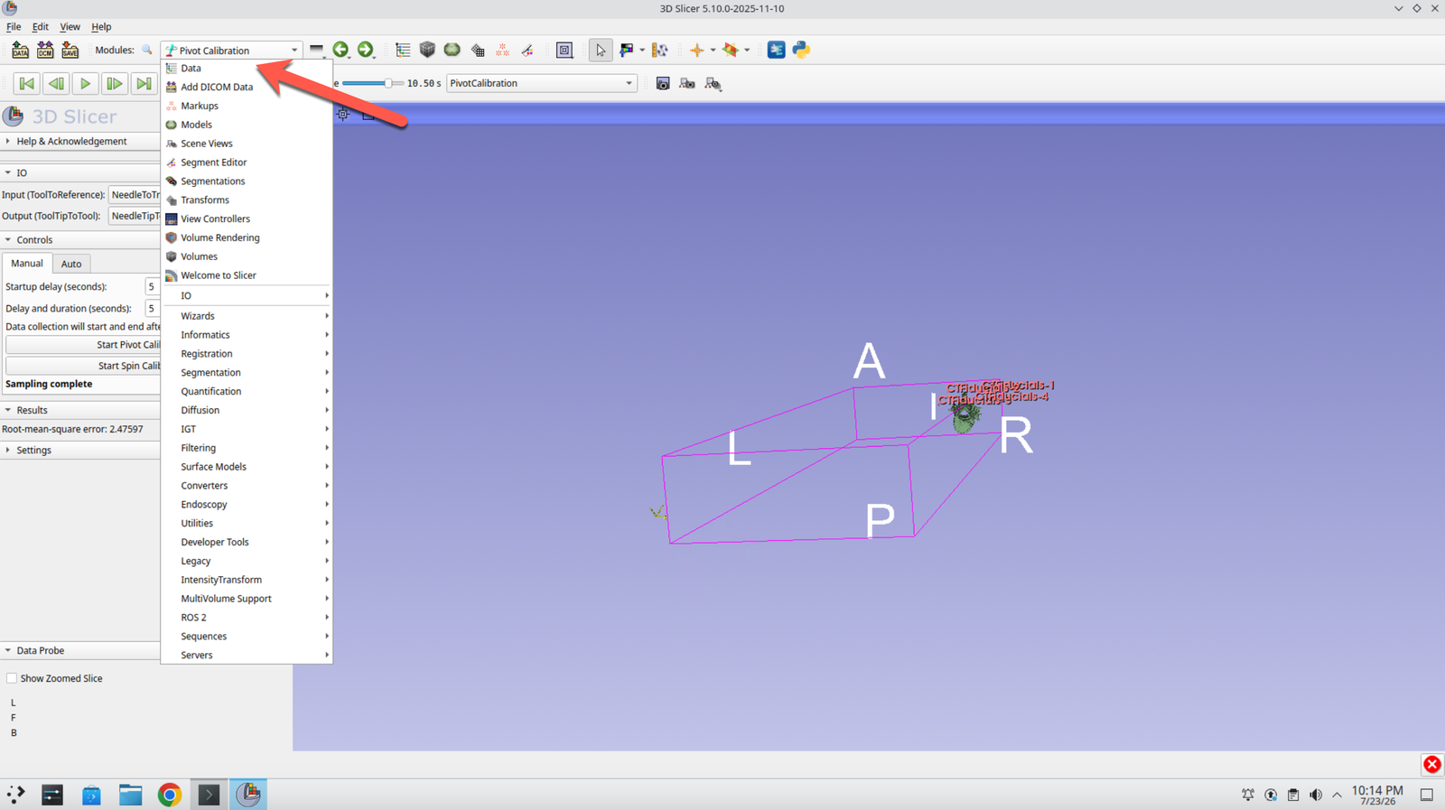
Step 30: Return to the Data Module
Switch back to the Data module.
Step 31: Attach the Calibration to the Needle Transform
Drag NeedleTipToNeedle onto the NeedleToTracker transform in the Data module, so the calibrated tip travels with the tracked needle.
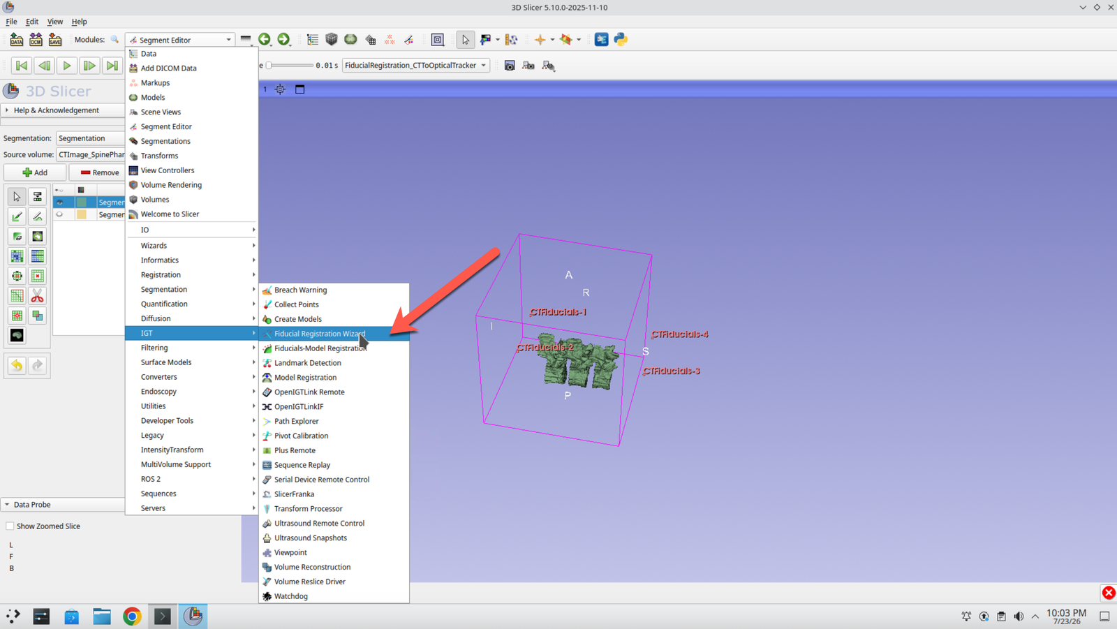
Step 32: Open the Fiducial Registration Wizard
Switch to the Fiducial Registration Wizard module.
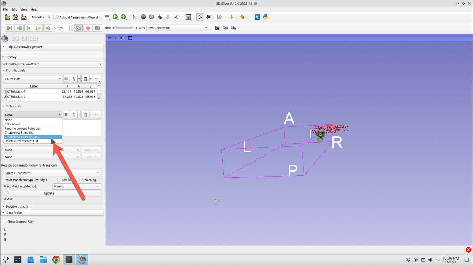
Step 33: Create the Target Point List
In the To Fiducials section, select Create new point list as….
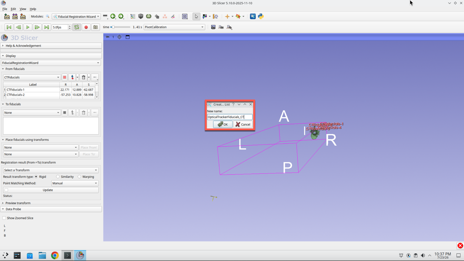
Step 34: Name the Point List
Call the new fiducial list OpticalTrackerFiducials_CT.
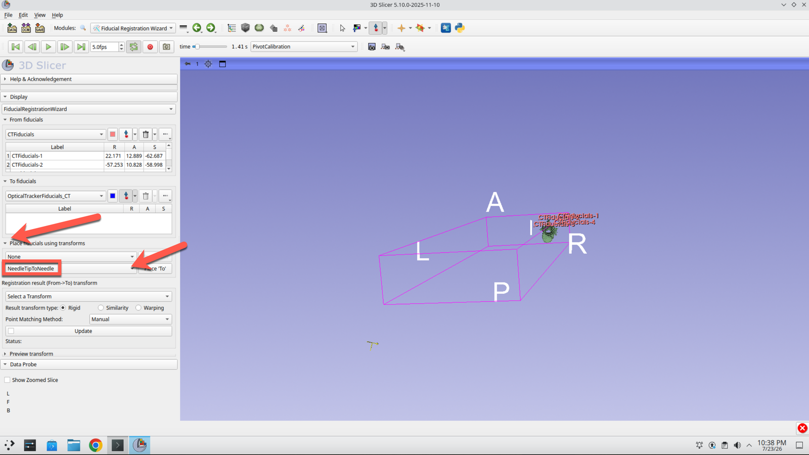
Step 35: Set the Placement Transforms
Expand Place fiducials using transforms and select NeedleTipToNeedle as the second transform. This means points are recorded at the calibrated needle tip rather than at the tracker marker.
Step 36: Select the Registration Sequence
Switch the sequence browser to FiducialRegistration_CTToOptical in the top bar.
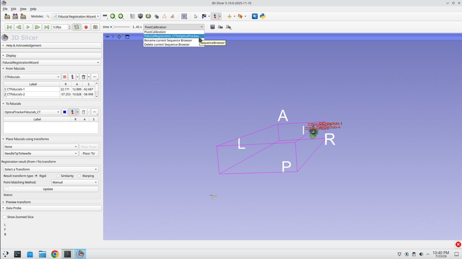
Step 37: Play the Sequence
Press Play to see the coordinate model move through the recorded registration motion.
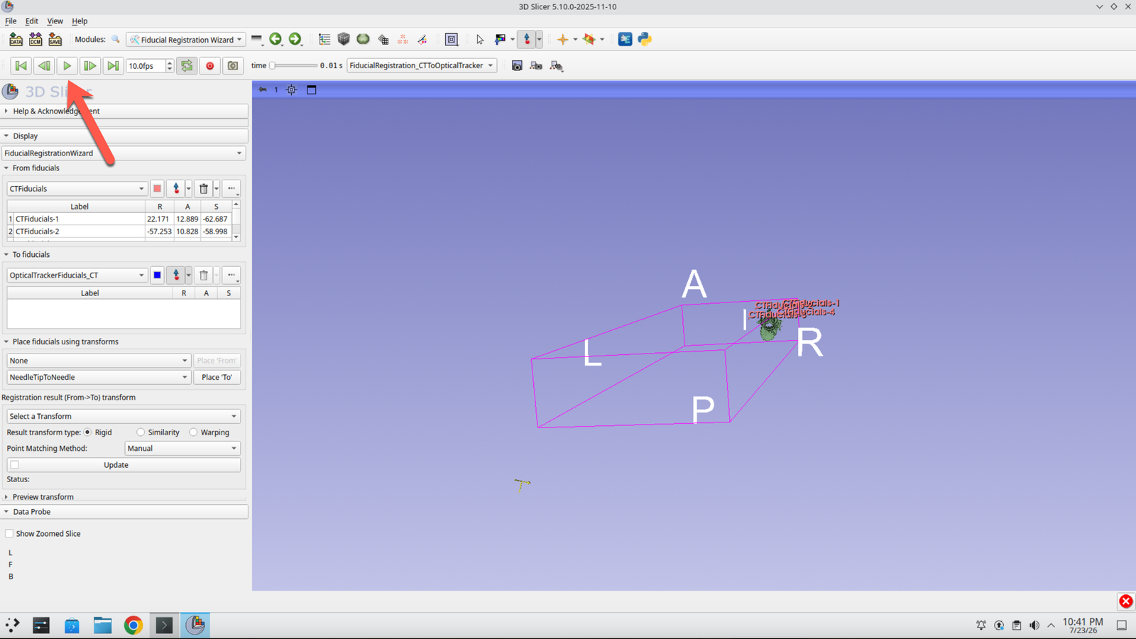
Step 38: Capture the Four Registration Points
Select the Place button as the sequence plays through the four registration points, capturing each corner of the gel block as the needle tip reaches it.
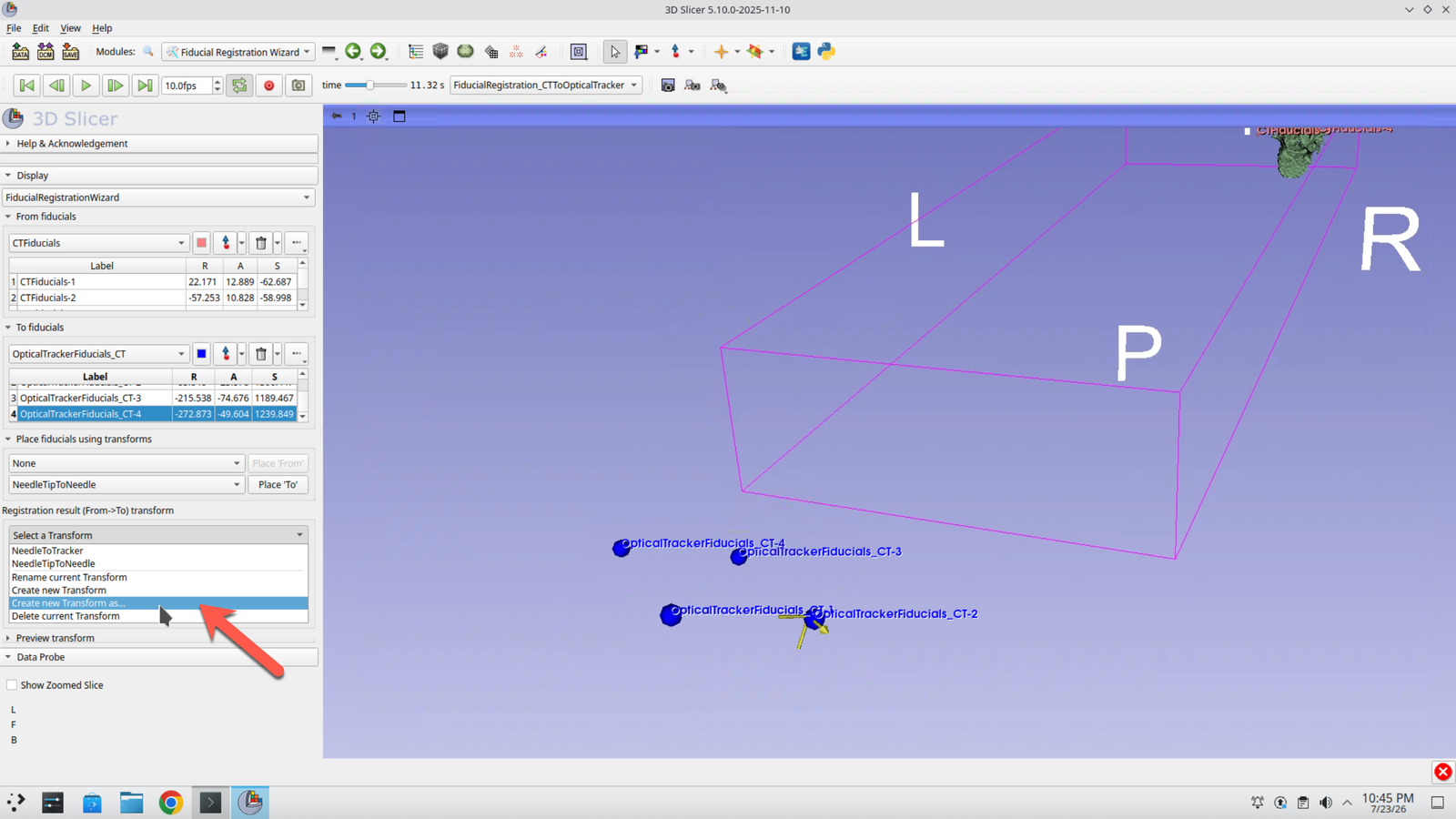
Step 39: Create the Registration Transform
Press Create new Transform as… to hold the resulting registration.
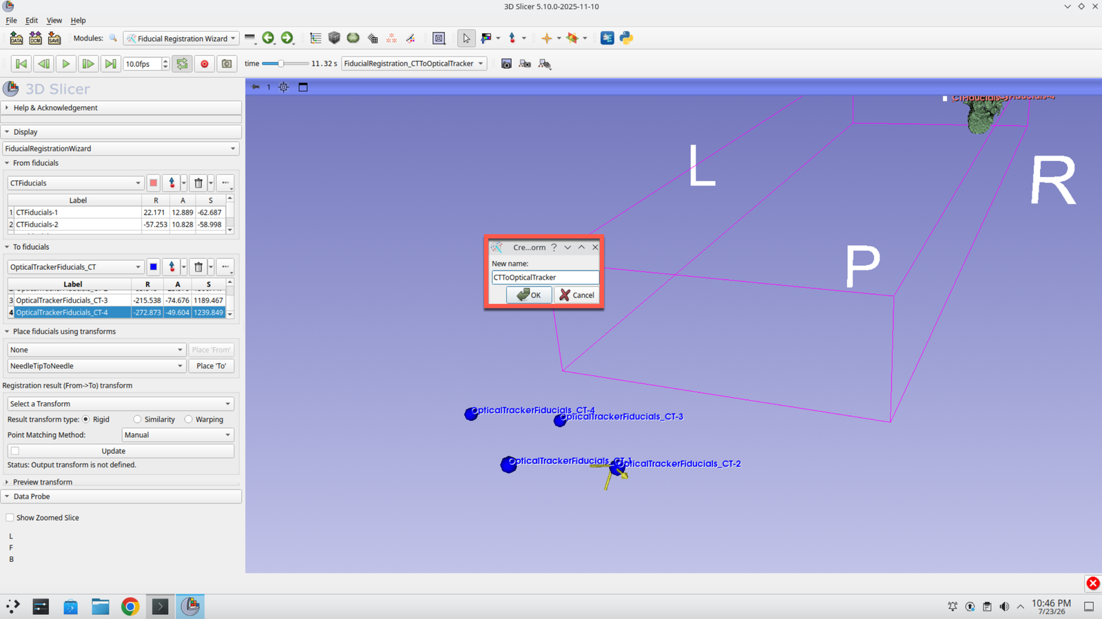
Step 40: Name the Registration
Call the registration CTToOpticalTracker.
Step 41: Update and Check the Error
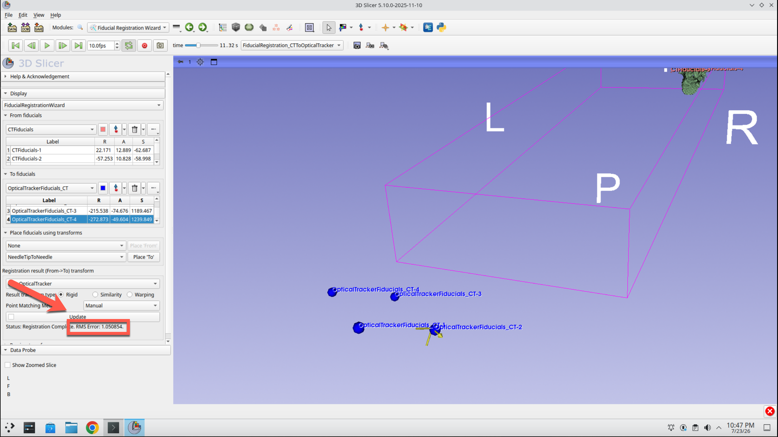
Press Update. A registration error value is reported at the bottom of the module panel — use this to judge how well the four points aligned.
Step 42: Return to the Data Module
Go back to the Data module.
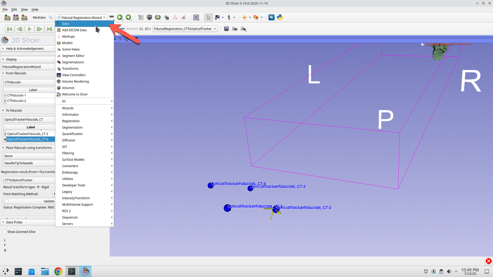
Step 43: Apply the Registration to the Anatomy
Drag the CT image and the segmentation onto the CTToOpticalTracker transform. The patient anatomy is now positioned in the optical tracker’s coordinate frame.